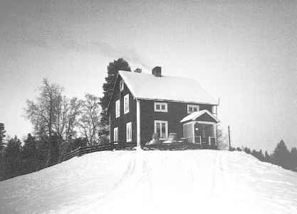
 Picture 1. A typical house in Northern Sweden
Project - Using Thermo-Electric Generation as a Simple Way of Generating a Limited Amount of Electric Energy
Author:
Anders J. Killander
anderski@cadcam.kth.se
Dept. of Manufacturing Systems
Royal Institute of Technology
100 44 Stockholm
SWEDEN
A report from The Department of Manufacturing Systems Royal Institute of
Technology Stockholm, SWEDEN
TRITA-TSM R-96-01 ISSN 1104-2133 ISRN KTH/TSM/R--96/1--SE
Abstract
In order to make electric energy available to families living off the grid in Northern Sweden, we have created and investigated different possibilities of generating small amounts of electric energy. To support this search for available principles and effects, we have used the Theory of Inventive Problem Solving, TIPS. By using TIPS we have been able to overcome the psychological inertia normally experienced in problem solving situation like ours. Several alternative concepts of electric generation were evaluated and thermo-electric generation, using the Seebeck effect, was finally selected.
A site survey indicated that ease-of-use and low maintenance were key success factors. The survey also provided thermal data as design input. A generator based on a fan-cooled unit that rests on top of a wood-fired stove was designed and several tests were performed to evaluate different parameters of the design. A prototype generator has been installed at a test site in Skerfa, Arjeplog County, and has generated electricity since November, 1995.
Through this project we have shown that it is possible to generate small
amounts of electric energy without introducing new resources to the existing environment.
The small fan- cooled unit on the wood-fired stove top can generate up to 100 Wh per day
without maintenance or noise, enough to feed low-watt fluorescent lights and a small TV.
1. Background
In Northern Sweden there are a few hundred families [TT] living in houses located in areas where the electric utility companies will not connect them. Offers for connection to the grid ranges from 5,000 to 120,000 USD [TT] . This is too much to be considered a sound investment for most families.
The government of Sweden supports this type of rural living, since it believes that a populated countryside is for the good of the nation. The support includes: phone service, postal service, schools with board provided for those who cannot commute, schoolbuses (which are sometimes snowmobiles, helicopters, etc.). The support entitles these families to pay the same basic charges for these services as anyone else in populated areas of the country. The postal service and the transport of children by helicopter to school is not a service that is provided daily to many families. These services are only provided on Monday and Friday. In this way, the children can spend the weekends at home with their families.
However, the support does not include electricity. Most of the homes are old mountain farms and have been in use (and still are) for many generations without electricity. The citizens of Northern Sweden are accustomed to life without electricity but, of course, desire some of the advantages and convenience that this type of energy brings. Today they use kerosene lamps and heat their houses by wood-fired stoves. Some of these families have invested in small-size, gasoline-powered Honda-type generators, but most of them think they use too much gas, are too noisy and need too much attention and repairs.
The electric generation by gasoline-powered units is also hard to use since the production and usage does not harmonize well. It is difficult to use the extra capacity of the gas-powered generators to charge batteries since the power output is high and the output is limited to a short period of time.
In research at the Department of Manufacturing Systems, Royal Institute of Technology, Stockholm, Sweden, new methods of generating solutions to difficult problems are being investigated. One problem that is being researched is the generation of a small amount (< several hundred Wh/day) of electric energy.
This problem was chosen mainly due to the fact that the author have used this example in lectures on problem solving to over 400 students, professors and engineers. During these lectures the audience have formed two main categories. One group that know that there are no new solutions but the one that they personally already know. Second, a group that can not solve the problem and find this very difficult, but admit that they probably do not know all possible principles and effects available.
These two categories together represent three important issues in difficult problem solving. First of all the problem of very strong psychological inertia, secondly the avoiding behaviour of engineers when facing contradictions and finally the lack of knowledge of principles and effects to solve problems.
The main focus of this project is to see if a good solution for generating limited amount of electricity can be found, using methods focused on basic principles. We also want to see if the tools and methods that we use can help us discover different ways to generate electric power.
The final step of our research in this case study will be to validate the proposed solution by building prototypes and use this in a field test. The test site and the prototype will be measured and monitored to check the performance of the solution. The results of this research is published in this report and as a conference paper in the 1996 International Conference on Thermo-Electrics. These publications will serve two purposes as follows:
1. It will show that the tools and methods that we use offers good
support in overcomming the problems that normally prohibits the engineers
in finding new solutions to difficult problems.
2. It will act as documentation and a recommendation as to how small-scale
electric-power generation can be made in certain situations, such as houses that are off
the power company's grid, but have access to a thermal energy source.
2. Initial Feasibility Study
In order to find available ways of generating electricity, we used common knowledge and the Theory of Inventive Problem Solving, from now on referred to in this paper as TIPS [TIPS]. We also used a TIPS-based software [TIPS SW] in order to make an efficient search of available principles and physical effects. We believe that we found some of these principles and effects due to the use of TIPS; principles and effects that would otherwise not have been found. The different types of electric generation concepts that were unearthed have been investigated during 1994 and early 1995. A summary of the findings is included below.
A survey was conducted in some family households in Northern Sweden prior to the start
and during the generator development activities of this project.
2.1 Different Generator Concepts
Phase change concepts * Water - steam conversions
* Sterling motors
Complex solutions, maintenance and cost (sterling engines) makes these concepts less
feasible. The basic, physical principles are refined but only some products are currently
available for domestic use on the market. No commercially available, volume manufacturer
of simple sterling motors has been found to drive down the cost of sterling technology,
which otherwise is a good candidate for this project.
Natural resources * Solar panels
* Small-size hydro-electric units
* Wind generators
Limited to no sun in the winter restricts the use of solar panels. The local rivers and
creeks are too small and frozen or nearly frozen in the winter; therefore, the water flow
is nonexistent or minimal at best, limiting the use of small-size hydro-electric units.
The wind conditions in Northern Sweden are low and unpredictable ruling out the use of
wind generators. However, technology is mature [Strong] and several products on the market
are currently available at reasonable cost. These solutions above may serve as a
complement to another system.
Combustion concepts * Gasoline / Natural gas/ Diesel generators
Noise, maintenance, lack of "ease-of-operation" and expensive gasoline (gasoline is presently 1 USD/liter in Sweden) have ruled out this type of generator. This solution is also a violation to a good solution, according to TIPS, since one will always try to find solutions that are based on the resources available in the system. New materials and energy sources will only be brought into the system if no other solution is feasible. The technology, nevertheless, is defined, and several products are currently available on the market.
There are also results that indicate that it is possible to burn natural gas and use
light-radiation to act on modified "solar panels" to generate electricity,
Thermo Photo Voltaic Generation [Valenti]. This way of generating electricity using
natural gas to generate light and not heat will, according to the initial results, be more
efficient than using the natural gas to heat a thermo-electric generator. There are,
however, no commercial products yet, and we still violate the TIPS rule to a good solution
by bringing in a new resource, natural gas, into our system.
Chemical electrical concepts * Phase/state changes
* Chemo-thermal devices
* Direct chemo-electrical devices
Currently, this is technology that is incomplete and underdeveloped. Not enough research has been done, as yet, for domestic use of these concepts. They are most certainly a feasible technology to be used in the next 10 years. A device that will use the chemically-stored energy in urine has been of great interest, but this device is not yet available [
Tsourikov].
Thermo-electrical concepts * Nernst-Ettinghauser effect
* Peltier/Seebeck effect
* Pyro/ferro electric effect
* Piezo effects
Many of these technologies are very promising but not yet entirely developed for
domestic use. The most feasible technology is thermo-electric generators, TEGs. TEG
technology is mature and there are several suppliers of Peltier elements/modules on the
market today. There are some European suppliers, as well as US and Russian suppliers.
2.2 Technology Selection
Based on the initial findings, we decided to continue our investigation of the thermo-electric generator based on the Seebeck effect. Once we knew what to look for, we searched the Patent Office [US patent 1, US patent 2] and conducted literature studies. It is important to note that unless we have knowledge of all known principles and effects, we don't know what to look for. For example, we will not find the Nernst Ettinghauser Effect scanning the Patent Office database for steam-turbine generators. This is why it is important to have tools like TIPS that will aid us in finding all known available principles and effects to base our concept on before we start to design a product.
Through the literature search we found some literature on thermo-electric generation [Bass et. al., Howell et. al., Supercool, Thornton, Global]. We also found different manufacturers [Melcore, Hi-Z]. After some initial contacts with different manufacturers, we decided to work with Hi-Z Technology located in San Diego, California, USA.
2.3 A Summary of the Site Survey - Typical Northern Houses
Typical houses in Northern Sweden are somewhat large. They are made of wood and are well insulated. See picture 1 below showing a conventional northern house. During the harsh winter season when snow and ice is present from November to May, some families do not heat the entire house, but stay in areas close to the kitchen where the main source of heat is located - the large, wood-fired cast iron stove.
Picture 1. A typical house in Northern Sweden
Due to the geographical location above the Arctic Circle, there are only a
few hours of daylight in the winter, and it is efficient to keep only one or two rooms
illuminated in order to save energy. The main desires expressed by our surveyed families
when seeking electrical solutions are as follows, in order of importance:
It was also expressed that if items 1-3 could be fixed, 95% of their desires would be
satisfied. In our opinon, as soon as they start to get some electric power, they would
want more. We were also surprised to find that neither a washing machine nor heated water
was on the list as a main priority. This may be due to the fact that most families always
have a large pan of heated water sitting on top of the stove.
2.3.1 Available Energy Sources
All houses are heated with wood-fired cast iron stoves. The easiest accessible thermal energy would be to use, in order of temperature:
In position #1 and #3 in figure 1 below, the temperature and flow of hot exhaust gas varies considerably over time, since it depends on the amount of logs that are burning at the time. Another point can be made at this time. If only self-induced air flow is to be used, then right above the stove the ambient temperature is, of course, slightly higher than the rest of the room. The same situation applies for the rear of the stove. Also in positions #1 and #3 below, the flow area of the exhaust outlet from the cast iron stove and the cross section of the chimney is, in most cases, 75-100 mm x 100-150 mm or the equivalent in diameter. In position #2 below, the available "excessive" stove top area is approximately 200 mm x 600 mm. "Excessive," in this case, meaning not normally used for cooking.
 Figure 1. Possible positions of a
thermo-electric generator
Figure 1. Possible positions of a
thermo-electric generator
2.3.2 Estimated Daily Use of Power
At the site selected for verification of this project, the Lasko family's farm in
Skerfa, Arjeplog, Sweden, the estimated daily usage is about 200-300 Wh. The estimate is
based on the use of 4-6 low-wattage lamps and a TV. One lamp, the kitchen lamp, will be on
most of the day, while the other lights will be on only a few hours a day, depending on
the situation. So, if generation can be regarded as almost constant for 12-14 hours a day,
a device producing 20-40 W would be sufficient considering losses in the DC/DC conversion,
the diodes and the battery charging circuit.
3. The Prototypes
During this project many different ideas and prototypes have been made. We will not go into detail to describe the evolution of the different prototypes. We will, however, describe the current, existing prototypes and the experiences that we have gained during this evolution.
The existing prototypes, #4 and #5, are both based on two-20 W modules each. The prototypes consist of five main parts: the slab or collector plate, the 20 W modules, the heat sink, the fan and the DC/DC converter, see below in figure 2.
 Figure 2. The
prototypes, basic design
Figure 2. The
prototypes, basic design
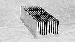
The difference between prototypes #4 and #5 is in the heat sink geometry. Prototype #4
has a heat sink with fewer fins, allowing the air to circulate easily, see picture 2
below. Prototype #5 has more fins to increase the heat dissipating area, which increases
the flow resistance of the air from the fan, see picture 3 below.
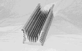
Picture 2. Heat sink of prototype # 4
Picture 3. Heat sink of Prototype # 5
3.2 Electrical Separation
The modules are separated from the collector plate and the heat sink by thermal grease
and aluminum oxide wafers, Al2O3. We also tried using thermal
conductive silicone rubber membranes as separators [Six Phase]. We got better readings
from the prototypes when using the AlO wafers and thermal grease than with silicone rubber
while using the same configuration and geometry. We have therefore only been using AlO
wafers in the later versions of the prototypes. All measurements listed in this report
were obtained from prototype number #4 and #5 using AlO wafers.
3.3 The DC/DC Converter
We have been using a DC/DC converter supplied by Hi-Z Technology. This is a 20 W converter with a wide range on the input scale and an adjustable output of
12-13.5 V. The input is also fitted with the possibility to adjust the voltage that you would like the unit to operate at. Since the thermo-electric modules have a very "peaklike" power characteristic, it is important to maintain the correct voltage in order to get the maximum wattage from the modules.
As a result, one can adjust the unit to get the best performance at any one given point. This is a problem in our case, since we use a wood-fired stove where the temperature of our hot surface is not constant. Consequently, we get many different points where we would like to maintain the DC/DC input voltage. Right now a "value in between" has been selected on the input. This setting will not give us the maximum wattage from the modules when the stove is very hot, nor will it be perfect for the temperature range that occurs at the end of each fire cycle. A small processor-based controller, which can detect the situation and adjust the input voltage accordingly, would certainly improve the output capabilities of the unit.
A small inconvenience with the present DC/DC converter is a high-pitched whining noise
that results from the switching frequency. This is not a loud noise, but still enough to
be irritating. We have solved this by encapsulating the DC/DC in a noise absorbing box
that still allows the air to circulate.
3.4 Parallel vs. Series Connection of the Modules
If we happened to be using the 20 W modules in a thermal situation similar to the maximum output data supplied by Hi-Z Technology, we would certainly connect the modules in parallel. This would fit the designed module voltage and the designed input voltage of the DC/DC converter. In our case, however, we do not have the same thermal situation, nor do we have a constant temperature. Since the module´s ouput voltage is temperature dependent, we need to find out if a parallel connection is still the best choice in our situation.
The stove top temperature varies between 100-300 C. Thermal losses do occur at each interface, which is between the stove top and the collector plate, between the collector plate and the AlO wafer, between the AlO wafer and the thermo-electric module's hot side, between the module's cold side and the AlO wafer and, finally, between the AlO wafer and the heat sink. Each interface represents a loss of 2-10 C. All these factors result in a lower temperature across the module than the maximum output temperature listed in the module's data sheet.
We have, therefore, conducted a series of tests to establish how we will connect the modules to achieve the best output wattage for our situation. From these tests, we have only been interested in the output wattage from the DC/DC. Another issue to take into consideration for testing is the physical phenomenon that thermo-electric modules have. They can be reversed and act as cooling devices (heat movers) if voltage and current is applied to the module. This is something that must be considered, especially if the temperature of the hot surface that the modules rest on is not uniform. This is uniform in space, over the surface, not constant in time. It is all right to change the temperature in time as long as the whole surface changes uniformly.
The following are some test data that was used during the research of this module. The test was performed during "normal" fire conditions; halfway between two log loadings into the cast iron stove. A load connected to the prototype consisted of the DC/DC, a 2.2 W fan and a 5 W fluorescent light. With the two-20 W thermo-electric modules connected in parallel, the maximum output wattage of 5.4 W was obtained with the DC/DC input voltage setting at 1.52 V. With the two-20 W thermo-electric modules connected in series, the maximum output wattage of 7.1 W was obtained with the DC/DC input voltage setting at 2.49 V.
The situation above repeated itself at other temperatures. Hence, our conclusions have
shown that in situations where the thermal profiles are similar to our test site, it is
recommended to connect two modules in series to obtain the most wattage from the design.
If a DC/DC converter with another working characteristic had been used, other conclusions
may have been drawn. This comment is also valid if the thermal profiles of other
applications or situations differs from our test site. Then again, other connection
alternatives may be better.
3.5 Fan Size and Position
In our prototypes we use two-20 W thermo-electric modules. The heat sink is roughly 100 mm x 300 mm, and there are several alternatives for the number of fans, fan size and fan position. We have worked primarily with small 12 V axial fans with 0.9 W, 1.6 W and 2.2 W. We have tried several configurations with one fan and with two small fans placed one above each module. We have also tried positioning the fan at the side of the heat sink to blow air from the side through the heat sink.
The conclusion so far is that one fan, 2.2 W, mounted above the center of the heat sink seems to work better than any other configuration. The single, larger fan produces a larger net wattage to the system, even though the fan draws more power than a small fan.
The sideways-positioned fan is OK, but the "fan side" of the unit must be facing a "free side" of the stove, so that the cooling air can be drawn from a "cool" location; otherwise, the fan will use air directly above the stove top. This limits the available position of the unit on the stove top. Also, we will get a thermal gradient in the "length" direction of the heat sink. The part of the heat sink closest to the fan will be cooler and the part at the far end will be warmer. This will result in different performances from the two modules, which is not desirable.
The top position is better from a performance point of view. We are free to position the unit at the optimal position on the stove top. This position may be dependent on the stove and exhaust gas outlet design. One disadvantage with the top- mounted configuration is the fact that we will use the air above the stove as our cooling air. As shown in figure 4, the ambient temperature 300 mm above the stove top is normally around +35 to +45 C. The fan will also be exposed to high temperatures with the top-mounted position, which will reduce the life of the fan.
4. Installation and Actual Data from the Test Site
To verify the feasibility and reliability of the prototypes, we have chosen to install a generator, prototype #4 and #5, in a house in Northern Sweden. The Lasko family in Skerfa have agreed to participate in a field test during the winter of 1995/96.
Rune and Ethel Lasko have a remote farm located by the Pite River in the northern part of Sweden. To access their house one must travel for quite some time in the outback of Northern Sweden. The last accessible roads are logging roads. When reaching Saddagava one must leave the car and go the last 11 kilometers by snowmobile through the forest (in case of winter conditions) or by boat down the river (in case of summer conditions when the river is not frozen). Winterlike conditions are normally present between late October to late May. Snowfall is usually 1.5 to 2 meters every year with temperatures down to -40 C below zero. The temperature was -27 to
-10 C during the installation and test for 3 days in late November, 1995.
4.1 Thermal Profiles on the Stove top
The temperature of the stove top varies both in space and time. Across the stove top,
the temperature differs depending on the distance from the actual point of fire and the
path of the hot exhaust gas flow. The temperature will also vary in time depending on the
time after a new load of wood has been placed into the cast iron stove. When it is very
cold the average temperature is higher on the stove top because loading new wood is more
frequent. The data captured and presented below represents the situation on Sunday,
November 26, 1995, when the outside temperature was between -10 and -14 C.
4.1.1 Stove Top Temperature Distribution
In order to establish where the thermo-electric generator should be positioned, a
series of measurements were taken to find the thermal distribution of the stove top. The
temperature on the stove top was taken at 4 locations, A to D, according to figure 3
below. Position E is a reference to the ambient temperature measurement.

Figure 3. Location of temperature measurements on stove top
A series of temperature measurements were taken at full fire and normal fire
conditions. Each measurement at full fire started 5 minutes after a new load of wood had
been placed into the stove and the fire was burning with full flames. In this instance,
the ash box door was wide open to increase combustion air flow. Each measurement at normal
fire started 15 minutes after loading the wood into the stove. During normal fire, the ash
box door was closed and the small vent on the door was open to allow for slow combustion.
No thermal loads (generator, kettles or pans) were placed on the stove top during this
test.
The following test results were obtained:
Position Full fire Normal fire
A 320-340 C 195-200 C
B 335-350 C 210-220 C
C 220-230 C 160-165 C
D 180-190 C 145-150 C
It may be noted that the hot gas exhaust exit out from the cast iron stove is located
right between location B and E at the rear of the stove. It was decided to use position B
as the position for the thermo-electrical generator. Partly this was due to its high
temperature, but also because this position will not interfere with the family's normal
use of the stove.
Position B on the stove top is the default position that we will use from now on for the thermo-electric generator, see picture 4.
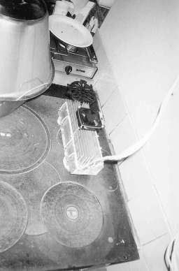
Picture 4. Prototype #5 in stove top position B
4.1.2 Temperature Distribution in Time
In order to see how the temperature varied in time, the prototype was equipped with thermal loggers and put on the stove. On the stove top, a Pt100 temperature sensor was positioned between the prototype collector plate and the surface of the cast iron stove top. This will reflect a "true" temperature in the area of the prototype, since the unit acts as a thermal load to the stove top. The ambient temperature measurement sensor was positioned 300 mm right above position E in figure 3. Finally, a Pt100 sensor was placed in the bottom of the heat sink. This reading was also used to check the ability for different fan configurations to keep the heat sink cool.
The result, shown in figure 4 below, indicate that the loading of wood has a cycle time of approximately 1 hour (given the outside temperature of -10 to -14 C). We can also see that the surface of the cast iron stove varies from roughly 150 C to 250 C during a cycle, with an average temperature of 185 C during the period
07:20 AM to 10:10 AM, November 26, 1995. The ambient temperature and the heat sink
temperature does not vary as much.
Figure 4. Typical thermal variation of the stove
top, bottom of heat sink and ambient air.
4.2 Operation and Output During Normal Fire
Under normal conditions, the generator will constantly generate 3-9 watts depending on the temperature of the stove top. The prototype is connected to a battery regulator circuit and 4 batteries via a diode that is placed between the DC/DC and the regulator. This connection will allow the generator to produce net power to the system, but never use any battery power.
When started, or fired up, the DC/DC will first feed the 12 V fan with power and then, as the output wattage increases, the system will receive the excess power. In this way, the fan is never connected to the system batteries and, therefore, neither uses any battery power, nor can the fan cool the generator when the self-produced wattage drops to low.
Our experience showed, after a few days of testing, that the best output is achieved in the early morning when the heat sink and the room temperature is low. This situation, in combination with frequent loading of new logs, can generate close to 10 W. However, a more stable situation is reached rather quickly and the prototype is soon generating only 4 to 7 W. This results in a net wattage to the battery system of
1 to 5 W, 0.1 to 0.4 Ampere at 13.0 V, after the DC/DC and the fan.
4.2.1 The Effect of Heat Sink Geometry on Wattage Produced
As we have mentioned before, the difference between prototype #4 and #5 is the geometry
of the cooling fins of the heat sink. In order to evaluate these two different designs, we
placed one prototype at a time in the same position on the stove and measured the thermal
and electrical situation so that the test occasions should be similar, see picture 5. Both
prototypes were tested with different fan configurations.
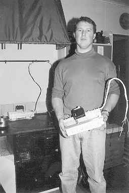
Picture 5. Test of both prototypes on the stove top
Our experience is that prototype #5, which is equipped with more and thinner heat sink fins, generates the best net wattage to the system. Prototype #4 was always
1-2 watts lower in output wattage.
The only time the prototypes were almost equal in power output was when we tried the fan configuration with the fan attached to the side. In this case, it was evident that the heat sink profile with more fins had considerable air-flow resistance.
The conclusion is that we will use prototype #5, with a heat sink that has many thin
fins, for the field test this winter.
4.3 Start Up Sequence
To see when the generator started working in the morning, the sequence that followed
the first load of wood was observed and measured. Both thermal data and wattage produced
was measured. See figures 5 and 6.
Figure 5. Temperature of stove top during a start up cycle
Figure 6. Output wattage produced during a start up cycle
The following are some observations with regard to figures 5 and 6 above. The fire was
lit at 07:01. At 07:08 the first attempt to fire up the stove failed and the fire faded. A
second, more successful attempt was made at 07:10. This can also be observed in the
thermal data of the stove top. The generator started to produce a net wattage to the
system at 07:27.
4.4 Cool Down Sequence
To find out how the generator worked with the fan and the DC/DC converter at the end of the day, the sequence that followed the last load of wood was observed and measured. Both thermal data and wattage produced were measured, see figures 7 and 8.
Figure 7. Temperatures of stove top and heat sink during a cool down cycle
Figure 8. Output wattage produced during a cool down cycle
Here are some observations taken with regard to the figures above. The generator
stopped producing a net wattage to the system at 22:58. From this point on, the unit only
feeds itself with enough power to run the fan. At 23:15, the wattage produced dropped
below the level where the fan would work properly. The fan stopped at 23:17. This is also
evident in the thermal data of the heat sink. As can be expected, after the fan has
stopped, the temperature of the generator increases in conjunction with the stove top
temperature.
4.5 Other Observations
When the 2.2 W fan is cooling the heat sink on the stove top, it causes the entire
room's air to move. This brings with it the decidedly positive result of less thermal
gradients in the room. Prior to the thermo-electric generator (with its fan), the stove
produced considerable heat and thermal radiation, but the temperature in the room was
somewhat cold on the floor and at a distance from the stove. Now there is a more uniform
distribution of the temperature in the room.
5. Some Valuable Hints
Below we have listed some hints that we have come up with during the development of the
thermo-electric generator prototypes. They may be used or just considered guidelines for
others who may want to build their own generator. Bear in mind that this is a list we
created from our experiences and it can probably be expanded upon with further research
and development of the prototypes.
6. Further Development and Improvements
These comments are mainly focused toward applications of thermo-electric devices. There is, of course, research and development in the areas of metallurgy and material science that may enhance the efficiency of the telluride alloys. Nevertheless, this does not affect the need for better design of the applications and devices that use these alloys.
There are three main areas where improvements can be made with reasonable effort. First, efficient cooling of the heat sink. Second, a DC/DC that can get the maximum output at every instant. Third, better thermal contact between the generator's "collector" part and the heat emitting surface.
Again, using TIPS, we will find that phase transformation is very good for heat absorption purposes. This will lead us to different ideas such as using heat-pipes or, more modern versions like heat-siphons, as something we believe should be explored further. Also, different types of water cooling would certainly be an improvement to air cooling, especially if warm water production is wanted in the system.
Regarding the DC/DC, a small embedded, microcontroller-based unit would certainly do the job without too much parasitic load to the system. The monitoring of the optimal voltage should not be a problem either. We may start development activities in this area as a student project.
Finally, regarding the heat transfer between the collector plate and the hot surface. As we have mentioned above, the geometry of the hot surface changes with time. According to TIPS, this will be solved with dynamism or compliant mechanisms. This has also been suggested by the engineers at Hi-Z Technology. One way to achieve compliance is to increase the degree of segmentation of the object; that is, let the generator consist of two or three modules, but let them be mechanically independent. Another way we can use compliant devices is by putting "things" in between the hot surface and the collector plate or by modifying either the collector or the stove top. In TIPS, this would be represented as an SU-Field situation where inadequate interaction between two substances will be solved by introducing "something in between".
This "something" can be fixed items or items that are segmented (as
mechanical parts) or very segmented (like strands, fibers or woven materials) or even more
segmented (paste, gels or phase transformations). A number of concepts based on these
ideas are many small spring-activated copper rods, copper wool, soft lead plates, a
mixture of copper beads and thermal paste. There is also the possibility to separate the
problem of space by making sure that the generator is stiff and bolted to the hot surface
to the extent that the thermal distortion occurs somewhere else in our system.
7. Conclusions
In order to find available concepts, principles and effects, the Theory of Inventive Problem Solving, TIPS, has been an invaluable tool. Without tools like TIPS, it is hard to say how many projects are started and finished without having complete knowledge of all known principles and effects that can solve the problem at hand. In all likelihood, many of these principles and effects are missed.
We have also shown from this project that it is possible to generate small amounts of electrical energy without introducing new resources to the existing environment. The small, fan-cooled unit on the wood-fired stove top can generate
50-100 Wh per day without any maintenance or noise.
It is evident that improvements can be made to the existing prototypes as well as modification to future generators. The important areas that would bring better efficiency to the generator are: better cooling of the heat sink, better thermal contact between the generator and the heat emitting surface and a DC/DC converter that can change its input voltage, thus, allowing maximum output wattage in a situation where the temperature is continuously changing.
We have found that the stove top location is good to use for small-scale electric
generation. Some advantages to the stove top location are: ease-of-access, a hot flat
surface, a large mass of cast iron and no harsh external environment. Unfortunately, the
cast iron stove itself has some drawbacks. Some disadvantages of the cast iron stove are:
its temperature is not uniform throughout, it changes its temperature depending on the
amount of fire that is burning, the ambient air above the stove is heated (this is to be
used for cooling) and the flatness of its surface changes as the temperature of the stove
changes.
Acknowledgments
The author would like to extend his thanks to Ericsson Radio Systems, The Swedish Wallenberg Foundation and the ISS90 Committee for their financial support, making this research possible. The author would like to thank Marianne Hofman for all photographs in this report. The author would also like to thank the following persons for their valuable comments and fruitful discussions: Professor Gunnar Sohlenius at the Royal Institute of Technology for his support and enthusiasm for basic principles of design. Valeri Tsourikov at Invention Machine Corp. for valuable discussions of concept generation; John Bass and Fred Levitt at Hi-Z Technology Inc. for their prompt answers to the never ending flow of questions from the author; Martin Ohlsson in Linkoping for acting as the project's electronics expert who was always at hand; and Christer Bloom at Profilgruppen in Spanga, Sweden, for supplying aluminum profiles for the project.
The success of this project has, to a large extent, been dependent on the author's
supporting and understanding wife, who every night for the past few months, saw her
kitchen (the stove in particular) transformed into a laboratory for heat transfer
experiments. Thank you, Lena.
References
TT "Hushĺll utan el kan elda fram egen ström", P. Vallgĺrda, Tidningarnas
Telegrambyrĺ, I0216, February 1996. (In Swedish)
TIPS Creativity As An Exact Science, G.S. Altshuller, Gordon & Breach, New
York, NY, USA, 1988.
TIPS SW Invention Machine, TIPS SW from Invention Machine Corp. Cambridge,
Massachusetts, USA
Strong The Solar Electric House, S.J. Strong, Sustainable Press, Still River,
Massachusetts, USA, 1993.
Valenti "Keeping the Home Fires Burning", M. Valenti, Mechanical Engineering,
pp. 66-69, July, 1993.
Tsourikov Personal communication with Dr. Valeri Tsourikov, Invention Machine Corp.,
1994 and 1995.
US pat. 1 US patent # 4,095,998 June 1978.
US pat. 2 US patent # 4292,579 September 1981.
Bass et al. "Performance of the 1kW Thermoelectric Generator for Diesel
Engines", J.C Bass, N.B. Elsner, F.A. Leavitt, Proceedings of the 13:th International
Conference on Thermo-Electrics, Kansas City, July 1994.
Howell Thermal Energy Systems: Analysis and Design, Howell, Bannerot, Vliet,
Solar. 2nd edition, McGraw Hill, 1994.
Supercool Product Information from Supercool AB, Gothenburg, Sweden, 1995.
Thornton "Reliable Power for Remote Areas", D. Thornton, Global Thermoelecric
Inc., Humble, Texas, USA, 1995.
Global Product information from Global Themoeletric Inc. Texas, 1995.
Global "The Theory of Themoelectric Generators, TEGs", Global Thermoelectric
Inc., Texas, 1995.
Melcore Product information and engineering catalog on ThermoElectrics from Melcore,
Material Electronic Products Corporation, Trenton, NJ, USA, 1994.
Hi-Z Product information on thermo-electric generator modules from Hi-Z Technology
Inc., San Diego, CA, USA, 1995.
Six Phase Product information on thermal conductive silicone rubber insulators from Six Phase Co. Ltd., San Chung City, Tapei, Taiwan, dated
May 10, 1988.
Appendix 1
List of tools and equipment used during the design, test and evaluation of the thermo-electric generators and the test site.
Digital Volt Meter: WaveTec DM 10XL (calibrated July, 1995)
TinyTalk temperature loggers with OTML Software to record and analyze the thermal data. (Loggers Calibrated September, 1995)
High temperature Pt100 probes and thermal grease (each probe calibrated in September, 1995)
Hand held Pt100 themometer CIE type 303K (calibrated August, 1995)