CASE STUDY ABSTRACT
Solving difficult problems is a complex activity that is governed by the search for knowledge. Problem solving is affected by a combination of the searching process and by the availability of the knowledge required to solve the problem. This paper describes the application of the Ideation/TRIZ Methodology and specific analytical and knowledge-base tools as used by DTM Corporation to solve a complex technological problem.
DTM CORPORATION
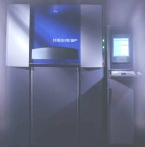
DTM Corporation develops, designs, manufacturers, markets and supports, on an international basis, rapid prototyping and rapid tooling systems and related powdered materials and services. DTM's Sinterstation systems use the SLS
® Selective Laser Sintering process to create solid three-dimensional objects, layer by layer, from plastic, metal, or ceramic powders that are “sintered” or fused using CO2 laser energy.TECHNOLOGICAL PROBLEM STATEMENT
The SLS
® Selective Laser Sintering process uses multiple applications to produce a three-dimensional part. DTM’s long-standing dilemma (seven years) was that the delivery of an essential system resource to the part bed is hindered by thermal distortion, adversely affecting the quality and reliability of the process.SLS® SELECTIVE LASER
IDEATION/TRIZ METHODOLOGY
Based on TRIZ (the Theory of Inventive Problem Solving), and advancements to TRIZ made by the Kishinev School and Ideation International’s Research Group, the Ideation/TRIZ Methodology includes applications related to the solving of inventive problems, failure analysis, failure prediction, and advancing and controlling the evolution of technological systems. This case study is limited to a specific application of the Ideation/TRIZ Methodology, called Inventive Problems Solving
Ô.THE IDEATION PROCESS AND ITS APPLICATION BY DTM CORPORATION
DTM’s first serious exposure to and utilization of TRIZ was based on the following educational and problem solving model:
§
DTM management committed to training and solving the stated technological problem (Craig Wadham, Director of System Development, DTM Corporation)§
Pre-training self-study of basic educational materials (“Learning Package 1” provided by Ideation International Inc.)§
Self-Sufficiency in Inventive Problem Solving training program (taught by Dana Clarke, Director of Education, Ideation International Inc.)§
Utilization of the Ideation Process and Innovation WorkBenchÔ System software (DTM team: Mark Chung, Chris Hanna, and Robert Welch)§
Post-training methodology coaching* of the DTM team for a period of 45 days by an Ideation TRIZ Specialist (Mark Barkan, Director of Analytical Services & Engineering)
* Post-training methodology coaching is an integral part of the educational process, and is not a consulting service. This support function is designed to provide new students of Ideation/TRIZ with expert advice on how the methodology should be applied to ensure that they achieve their goal.
Utilization of the Ideation Process
STEP 1. PROBLEM DOCUMENTATION AND PRELIMINARY PROBLEM ANALYSIS
The Ideation Process begins with a six-part questionnaire called the Innovation Situation Questionnaire™ (ISQ™). The ISQ is a template for preliminary problem analysis, and consists of a set of questions that help define at the problem situation from a different point of view. These questions are not typical engineering- or management-oriented questions, but are innovation oriented, resulting from years of accumulated research in the successful application of TRIZ-based methods and tools in the solving of inventive problems. The questions in the ISQ provide the problem solver with a systematic way to approach the problem situation, and prompt him/her to consider things that are typically disregarded or go unnoticed during problem solving. Interestingly, 10% of the time the ISQ alone is enough to resolve the problem.
The questionnaire contains six main categories:
1.1. Information about the system
· System name, system structure, functioning, primary useful functions, reason the primary useful function is performed, system environment
1.2.
Information about the problem situation·
Problem to be resolved, undesired consequences if the problem remains unresolved, mechanism causing the problem, history of the problem (how and when it occurred), other problems to be solved if this problem is unsolvable, ideal vision of the solution
1.3. Changing the system
·
Allowable changes to the system, limitations for changing the system
1.4. Available resources
·
Resources having to do with substances, fields, functions, information, time, space, flow
1.5. History of attempts to solve the problem
·
Previous attempts to solve the problem, other system(s) in which a similar problem exists
1.6. Criteria for selecting Solution Concepts
·
Desired technological and economic characteristics, desired timetable, expected degree of novelty, other criteria for evaluation
DTM Innovation Situation Questionnaire (ISQ)
Prior to the Self-Sufficiency in Inventive Problem Solving training session, the Subject Matter Experts for DTM completed an ISQ (not shown). This pre-training ISQ ensured that the defined problem was suitable for Inventive Problem Solving using the Innovation WorkBenchÔ System software.
The following ISQ was developed following the Subject Matter Expert training session.
Innovation Situation Questionnaire
Revised after DTM
Subject Matter Expert Training
1. Document the problem
General description of the company business environment.
DTM's Sinterstation systems use the SLS® Selective Laser Sintering process to create solid three-dimensional objects, layer by layer, from plastic, metal, or ceramic powders that are “sintered” or fused using CO2 laser energy. The inherent materials versatility of SLS technology allows a broad range of advanced rapid prototyping and manufacturing applications to be addressed. From aerospace to consumer electronics and automobiles to appliances, companies around the world use DTM's Sinterstation systems to accelerate the design, development, and market introduction of new products.
Functional Modeling. With DTM's rapid prototyping technology, prototype parts are created directly from engineering plastics and thermoplastic elastomers. These parts are used for demonstration and testing purposes in a variety of applications. They can snap-fit, form living hinges, accept fasteners and be mounted with motors, circuit boards and other components.
Prototype Manufacturing: DTM’s patented technology allows for the creation of prototype tooling and patterns for a variety of manufacturing processes. Applications supported include injection molding, die casting, sand casting and investment casting.
Please refer to http://www.dtm-corp.com/Technology/sls_process.htm for an excellent description of the technology and mechanisms involved.
2. Information about the system
2.1. System name. Powder delivery system
2.2. System structure.
The powder delivery system contains:
Part piston
Feed pistons
Part bed powder
Part bed heater
Feed bed heater
Roller
Feed powder
Other parts of the powder delivery system
Cylinder heater
Fused part
Other systems interacting with the powder delivery system: Laser, nitrogen
2.3. Functioning of the system
In a nitrogen environment:
- Feed heater heats the powder in the feed pistons (feed powder)
- Feed piston increments upward a set amount of powder
- Part piston increments downward one layer thickness
- Roller distributes the feed powder to the part bed
- Part heater heats the part bed powder to operating temperature
- Laser selectively fuses the part bed powder together, forming a solid object
Other factors affecting the part bed powder temperature are the cylinder heater and the fused part.
2.4. Primary useful functions. The primary useful function of the powder delivery system is to distribute hot powder to the part bed within a few degrees of the powder melt point to minimize curl/thermal distortion.
2.5. Reason to perform the primary useful function. To decrease the temperature differential between the feed powder and part bed powder, and to provide a uniformly dense layer of hot powder to the part bed.
2.6. System environment
- Process chamber encloses the part, feed, and powder mechanisms.
-
Nitrogen inert atmosphere within process chamber.-
Dust environment.-
Minimal forced convection from nitrogen input.-
Forced air circulation capable but not used.3. Information about the problem situation
3.1. Problem that should be resolved. Inability to deliver hot powder to the part bed to within a specified temperature range for processing.
3.2. Undesired consequences of unresolved problem. Dimensional variation.
3.3. Mechanism causing the problem. The flow properties of powder change at high and low temperatures.
3.4. History of the occurrence of the problem. The powder delivery system has not changed since the machine's inception.
3.5. Other problem(s) to be solved if this problem is insolvable.
- Alternate delivery method to produce uniformly dense layer of hot powder.
- Increased uniformity in part bed thermal distribution
3.6. Ideal vision of solution
Mechanism that delivers powder uniformly and quickly at the processing temperature.-
4. Changing the system
4.1. Allowable changes to the system. Looking to find a solution for the next generation machine and thus changes are not limited to existing hardware or technology.
4.2. Limitations for changing the system
- Cost effective: must not exceed cost of the existing system.
-
Must not decrease the throughput of the existing machine.-
Must be robust.-
Must work with existing powders.-
Must not cause powder segregation.-
Refer to “Success Criteria” (determined to be company confidential) for more information
5. Available resources
5.1. Substance resources
Roller
Part piston
Feed piston
Part heater
Feed powder
Feed heater
Nitrogen
Fused powder
Part bed powder
Laser
Part cylinder heater
Forced air circulation system
Hinged thermal isolators (swing gates)
Ethylene glycol based cooling system
5.2. Field resources
Thermal energy
Mechanical energy
Electrical energy
Laser energy
5.3. Functional resources
Unfused powder supports fused object in part cylinder.
5.4. Informational resources.
- Fields irradiated from the system and components: audible and electrical noise, heat, vibration, static electricity.
- Materials emitted from the system: dust, volatiles, monomers
5.5. Time resources
- Thermal stabilization time
-
Layer creation time-
Process chamber cool-down time5.6. Space resources. Machine footprint and part bed dimensions.
6. History of attempted solutions to the problem
6.1. Previous attempts to resolve the problem.
- Lower feed temperature setpoints - temperatures lowered to increase powder flow. Piston heater - added to minimize heat loss through bottom of part piston. Discontinued due to lack of benefit after approximately 1 inch.
- Cylinder heater - added to minimize heat loss through walls of part bed chamber.
- Air pulled through part chamber - vacuum pump sucked air through part cake.
- Different powder formulation - various chemical compositions and additives which allow easier processing.
6.2. Other system(s) in which a similar problem exists. Unknown
7. Criteria for selecting Solution Concepts
7.1. Desired technological characteristics.
Mechanism that delivers powder uniformly and quickly at the processing temperature.
7.2. Desired economic characteristics. Equal or better than existing.
7.3. Desired timetable. Unspecified.
7.4. Expected degree of novelty. Unrestricted - no patent or licensing issues
7.5. Other criteria for evaluation
Works with multiple materials
Machine throughput
Uniform delivery of powder layer
Minimal waste of powder
Refer to “Success Criteria” (determined to be company confidential) for more details.
8. Additional information, explanation, comments, etc. None
9. Project data
9.1. Project name. Powder delivery system
9.2. Project objectives. Improve powder delivery system
9.3. Project timeline. One month
STEP 2. PROBLEM FORMULATION
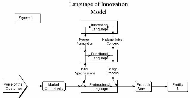
Problem formulation begins with the development of a graphical model consisting of the events and conditions - in terms of cause-and-effect relationships - that comprise the problem situation. While this might appear to be similar to functional diagramming, it differs inasmuch as it provides for a new level of creativity in the search for (and implementation of) solutions. The functional language of Value Engineering allowed engineers to move beyond their professional language to a “common” language that had relevance to marketing and the needs of the customer. Problem formulation provides a similar language transformation: one that transforms a functional language to an innovation language (see Figure 1).
The process of moving from a functional language to an innovation language introduces additional levels of refinement and comprehension of the problem situation. The underlying benefit is that, when a situation is formulated (or, more accurately, reformulated), the solution often becomes obvious or is more easily obtained than through the initial statement of the problem situation. The process of problem formulation is the continued through “slicing” of a complex or unclear situation into a comprehensive set of well-defined problems. Directly attacking each “slice” is the key to the successful generation of ideas and, consequently, to the development of implementable solution concepts.
The notion that a problem situation can be explicated into multiple problem statements is rooted in Altshuller’s “multi-screen” model of creative thinking, a.k.a. the systems approach. This approach holds that any system has a hierarchical structure that includes subordinate sub-systems and at least one higher-level system (the so-called “super-system”) to which it, in turn, serves as a sub-system. Very often, the links between these systems, sub-systems and super-systems are rigid enough to ensure that a change in one part of the system causes substantial changes (either positive or negative) in other sub-systems and in adjacent systems as well. In particular:
·
A breakdown in one part of the system can cause undesired consequences in other parts of the system, and in the system as a whole.·
An undesired situation in one part of the system can be eliminated by changing a different part of the system
.
As a result, one problem can be addressed in different, and often greatly diverse, ways. Put another way, the assertion can be made that there is always more than one way to approach a given problem.
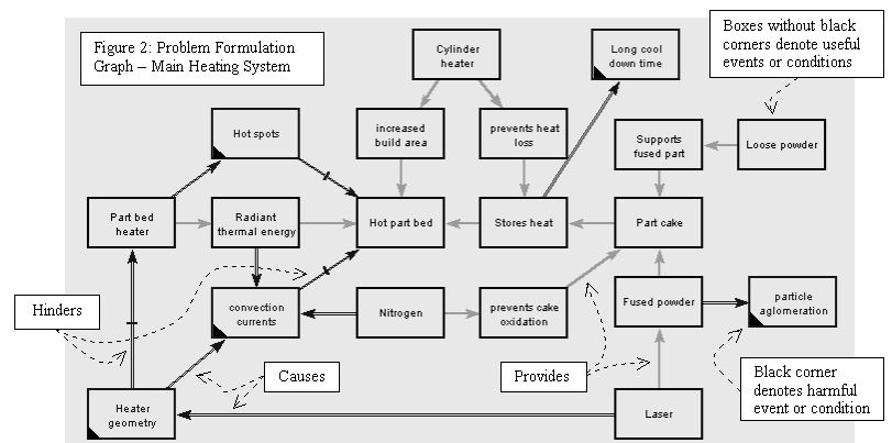
Problem formulation further differs from traditional functional diagramming in that it includes harmful events and conditions as well as useful ones. The developers of the problem formulation process, Boris Zlotin and Alla Zusman, determined that by combining functional diagramming, which addresses useful functions, and Ishikawa (“fishbone”) diagramming, which deals with harmful functions, new benefits could be realized (see Figure 2). Figure 2, one of several diagrams developed by the DTM team, was leveraged through the use of a patented software algorithm that provides an exhaustive set of Directions for Innovation, replacing the need for trial-and-error attempts. The Directions for Innovation are the representation of a single, complex problem by a set of simple (and more easily solved) problems. In effect, problem formulation constitutes a “map” of the problem situation (i.e., the events and conditions that constitute or relate to the problem) in terms of cause-and-effect relationships.
Problem Modeling and Knowledge Conversion
What is occurring when we model a problem situation? For most of us, the knowledge we possess about a particular problem (or any situation) is not segmented into precise, orderly units that can be easily represented with pencil and paper, or even with a computer. Rather, it resembles a monolith of complicated interconnections and “chunks” of information, intermixed with an assortment of associations from the useful (possible solutions, analogous situations, similar problems, etc.) to the distracting (such as emotional factors or extraneous job-related issues).
Modeling a problem is a process - sometimes a lengthy one - of converting this mass of mental data into an ordered collection of sequential “knowledge units,” and of determining the relationships between these units. A reasonably modeled problem can convey all the necessary information about a problem situation - and then some.
The benefits of problem modeling as incorporated in the problem formulation process are as follows:
§
Its use provides increased understanding of a problem situation and thus affirms the TRIZ adage: “A correctly formulated problem is a problem that is nearly solved.” Moreover, the building of models that reveal an exhaustive set of Directions for Innovation is an expeditious way to gain this increased understanding, making the modeling process a “quick learning” tool.§
Within the exhaustive set of Directions for Innovation generated by the problem formulation process are those that are non-obvious and, therefore, would likely have been overlooked.§
The process helps to break down psychological inertia by providing a means for the user to view the problem outside of his/her familiar, technology-specific domain.§
An important outcome of this approach is a set of comprehensive and transferable documents of the situation and related opportunities for innovation.
The “Language” of Functions and Links
The problem formulation model is composed of two main elements: functions and links. A function consists of a box that includes text describing something about the problem or system. Functions represent an event or condition in the form of an action, component, condition, process step, etc. A link, represented by an arrow, describes the relationship between two functions.
There are four types of links in the model:
Provides (a single line arrow)-
-
Causes (a double line arrow)-
Hinders (a double line arrow with a crossbar)-
Eliminates (a single line arrow with a crossbar)These simple ingredients provide the “language” necessary to adequately describe any problem situation for the purpose of developing solution concepts. The situation can be either technical or non-technical; the latter opens the door to working with business process improvement and re-engineering situations.
Note: In Figure 2, only two of the above four links are used: provides (a single line arrow) and hinders (a double line arrow with a crossbar). There are four boxes in this diagram (2a, 2b, 2c and 2d) that provide a useful while also hindering something - these boxes have desirable characteristics but also produce harmful effects. This situation is referred to in TRIZ as a contradiction.
Directions for Innovation - What Are They?
One of the reasons complicated problems are difficult to solve is that they cannot be solved “in a single shot” - indeed, attempts to do so prove frustrating and fruitless. The experience of successful inventors shows that complex problems require a multi-faceted approach, something that the “normal” mental process cannot effectively accommodate.
To support solving of complex problems, the Ideation Process helps separate them into a set of simple problems known as Directions for Innovation. Successive tackling of these problems is the equivalent of the multi-faceted approach used by successful inventors. This approach consists of looking at a problem situation from all possible points of view.
The following computer-generated Directions for Innovation are based on the DTM’s Main Heating System Problem Formulation shown in Figure 2.
Directions for Innovation and Associated Ideas
DTM’s Project Team compiled more than 120 directions and associated ideas to resolve the hot powder delivery issues associated with the
SLS® Selective Laser Sintering process. The following samples illustrate how the Ideation Process and the Innovation WorkBenchÔ System software helps to provide focus and new opportunities for innovative solutions. Each Direction provides an entrance into the software knowledge base of operators and associative chains of operators, which emulate the way great innovators think.Direction: Find a way to do without the (Part bed heater) for obtaining (Radiant thermal energy).
Associated Idea:
Put heater on the rollerDirection: Find a way to protect the (Hot part bed) from the harmful influence of (convection), (hot spots in part bed), and (Warm powder).
Associated Idea: Eliminate the dead air space behind the process chamber to increase the ambient air temperature
Direction: Find a way to resolve the following contradiction: the (Part bed heater) should exist to obtain the (Hot part bed), and should not exist in order to avoid the (hot spots in feed powder).
Associated Idea: Decrease distance from part bed heater to part bed
Direction: Find a way to do without the (Part bed heater) for obtaining the (Hot part bed).
Associated Idea: Microwave the part bed.
Associated Idea: Powder additives that add heat when hit by laser
Direction: Find an alternative way to obtain [the] (Nitrogen), that provides or enhances [the] (Previous layer), and does not cause [the] (convection).
Associated Idea: Rough vacuum.
Associated Idea: Increase chamber ambient temperature.
Associated Idea: Heat the process chamber floor
Direction: Find a way to resolve the following contradiction: (Nitrogen) should exist to obtain the (Previous layer), and should not exist in order to avoid (convection).
Associated Idea: Updraft through the part bed with hot nitrogen for positive pressure to deflect cold convection currents
Direction: Find a way to protect the (Smooth layer) from the harmful influence of the (Feed heater).
Associated Idea: Two section angled feed heater to prevent cross talk to part bed.
Associated Idea: Heated grate in top of feed opening instead of radiant heater panel with thermocouples to regulate the temperature. Add deflector to feed heaters
Direction: Find a way to do without the (Smooth layer) for obtaining the (Good part bed).
Associated Idea:
Coarse apply the hot powder toothed roller and then smooth with a secondary roller. Normalize the wavy part bed.Direction:
Find an alternative way to obtain the (Feed piston), that provides or enhances the (Warm powder).Associated Idea: Use a knurled roller with high counter rotation speed to fluidize the powder wave.
Associated Idea: Dispense powder in a metered wave, feed smaller amount, break up large wave into smaller wave(s).
Associated Idea: Double small roller, double small wave top feed.
Associated Idea: Triple small roller, double small wave top feed.
Associated Idea: Caterpillar heated feed.
Associated Idea: Angled belt feed.
Associated Idea: Planetary roller feed.
Associated Idea: Crop row feed with secondary roller to fill in the furrows.
Associated Idea: Spline shaft feeder with trailing roller.
Associated Idea: Helical spline shaft roller.
Associated Idea: Spline roller with trailing front-to-back vibrating blade (sets layer thickness).
Associated Idea: Heated snow globe feeder.
Associated Idea: Fluidize powder wave with heated nitrogen.
Associated Idea: Dense phase traversing pneumatic feed.
Associated Idea: Compressed powder and cheese slicer feed.
Associated Idea: Dual laser 3D fabrication using intersecting interfering lasers; sintering occurs only at the intersection of the beams.
Associated Idea: Sub-layer sintering
Direction: Find a way to enhance [the] (Hot part bed).
Associated Idea: Increase radiative coupling between part heater and part bed.
Associated Idea: Increased coupling of cylinder heater.
Associated Idea: More uniform part bed thermal distribution
Direction: Find a way to protect [the] (Hot part bed) from the harmful influence of [the] (convection currents) and (Hot spots).
Associated Idea: Decrease the dead air space behind the process chamber.
Associated Idea: Add condensers to collect fairy frost (ease of cleaning essential).
Associated Idea: Increase the thermal conductivity of the powder.
Associated Idea: Rotate the heater like a rotisserie.
Associated Idea: Rotate heater very fast and fire laser through it like a propeller.
Associated Idea: Oscillate the heater focus like a fan (up and down).
Associated Idea: Move heater rod side to side and scan at trailing edge.
Associated Idea: Mount heater to roller and fire laser horizontally behind the heater/roller; Roll, heat and sinter in one motion.
Direction: Find an alternative way to obtain [the] (Part bed heater), that provides or enhances [the] (Radiant thermal energy), but does not cause [the] (Hot spots). This way should not be influenced by [the] (Heater geometry).
Associated Idea: Fire laser from the side of the process chamber to drop the chamber height and eliminate the hole in the heater.
Associated Idea:
Solid heater and split laser beam to both sides.Associated Idea:
Köler lens heater.Associated Idea: Print head that deposits a laser absorbing material and the diode bar laser that sinters, both mounted on an XY plotter scan system.
Associated Idea: Charged particle electron beam steering ionized plastic particle accelerator machine.
Direction: Find a way to enhance [the] (Part bed heater).
Associated Idea: Find a different supplier.
Associated Idea: Segmented part bed heater with Köler illumination.
Direction: Introduce a field-intensifier to enhance the action of the (Radiant thermal energy).
Associated Idea: Add material to powder that enhances the absorption of thermal energy
Ideation comment: this direction and idea confirms that the SMEs are developing a greater understanding of the methodology.
Direction: Provide better controllability to enhance the action of the (Radiant thermal energy).
Associated Idea: Alternate control scheme, fast heater, slow heater, decrease the distance from heater to part bed
Direction: Increase the level of ideality of the object of the (Roller).
Associated Idea: Deliver powder without agitating/shearing it.
Associated Idea: Powder can be compacted and laid onto part bed like a sheet of paper.
Associated Idea: Translating belt feeder with belt surface velocity equal to the traversing velocity.
Associated Idea: Vibratory top feed hopper. Flow rate past chute is matched to traverse velocity.
Associated Idea: LOM-style system which uses heat to fuse layers together.
Associated Idea: User laser to create powder. Use dot matrix firing pattern to weaken sheet so that part can be broken out.
Associated Idea: Extrude slurry/powder through nozzle such that thickness of stream equals to layer thickness. Match the traversing velocity of nozzle to the stream velocity exiting the nozzle.
Associated Idea: Foamed plastic from heated nozzle
Ideation Comment: Here they are beginning to see similarities to copy machines and laser printers
STEP 3. PRIORITIZATION OF DIRECTIONS FOR INNOVATION AND GENERATION OF IDEAS
DTM’s Subject Matter Experts prioritized the directions by visual analysis of the Problem Formulation diagram, and then selected the directions of particular interest.
Once Directions for Innovation had been prioritized the Innovation WorkBench
Ô System software was used to generate ideas.Utilization of a Structured Knowledge Base
As was stated earlier, TRIZ is a science - one that has resulted from over 50 years of research. This research is ongoing and, to date, consists of the extraction and structurization of knowledge from two primary sources: over two million worldwide patents, and the history of technology itself. Research has been the identified principles, methods and patterns that have recurred time and again throughout history. The extent and complexity of this accumulated knowledge was the driving force for using computer technology in order to efficiently and effectively put this wealth of knowledge to use.
For technological problems such as the one resolved by DTM, access to this knowledge base provides a significant advantage over traditional brainstorming, which is typically dependent on the talent of the facilitator and the knowledge of the participants. By integrating the process of problem formulation (including the generation of Directions for Innovation) with the use of an extensive knowledge base, the DTM team had the ability to quickly focus their creative abilities on specific information directly related to their situation.
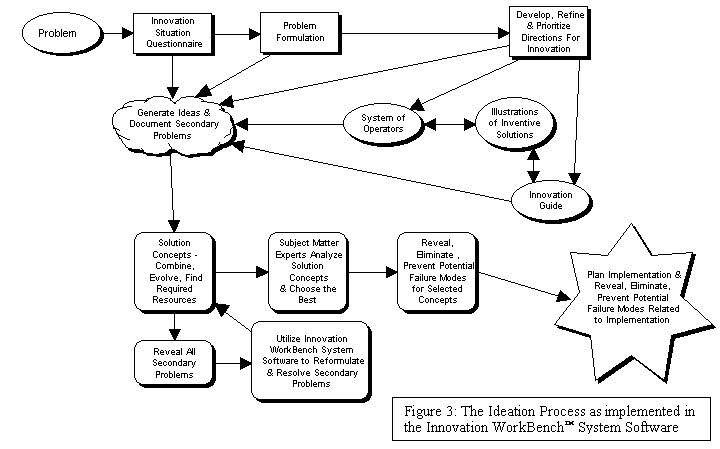
Figure 3 shows the structure of the Innovation WorkBench™ System software developed by Ideation International Inc. This software incorporates the Ideation Process, which in turn encompasses the Problem Formulation process. In Figure 3, the rectangular nodes represent analytical tools, the oval nodes represent knowledge-base tools, the cloud node represents the accumulation of ideas and secondary problems, and the rounded-corner nodes indicate those components of the software that support the effective conversion of ideas into implementable concepts. The final component of the software, denoted by the star-shaped node, represents the part of the process where implementation of the final concept(s) is analyzed and planned.
The cloud-shaped node in Figure 3 represents a significant point of differentiation between the Ideation Process and traditional brainstorming. Traditional brainstorming (which is based on the work of Alex Osborn) separates idea generation from the critique and evaluation of the ideas. Extensive psychological research by TRIZ scientists has revealed that this is effective for solving low-level problems, but not for solving complex technological problems. These findings are based on two factors:
·
It is “natural” for humans to critique ideas as they occur - efforts to block this natural tendency has a psychological effect on the individual that hinders the natural creative process.·
By stating and documenting secondary problems, we accomplish two things; first, we clear the mind to think freely about new ideas; and two, we “charge” the mind with secondary problems. This process of “charging the mind” prepares us to solve problems which, in many cases, are easily solved (in fact, secondary problems are often easier to solve than the primary one to which they relate). When working with TRIZ, we are continuously reformulating problems and solving both primary and secondary problems. This process allows for the development of a broad cross-section of ideas and, when necessary, a nearly exhaustive set of ideas can be developed into an exhaustive set of concepts.The DTM team diligently followed this process, continually expanding their knowledge and charging their minds with the information required to solve not one but several problems.
STEP 4. DEVELOPMENT OF CONCEPTS
In preparation for developing concepts, the DTM team utilized affinity diagramming to group ideas. The team then followed this process by creating a matrix, which allowed them to quantify each of the ideas based on a predetermined set of success criteria. The actual results of the team’s work are confidential and therefore cannot be published. What is critical, however, is that the team followed each step of the Ideation Process as defined in the remainder of this case study.
The rationale for this part (i.e., “Development of Concepts”) of the Ideation Process is the notion that it is a rare occurrence that one idea resolves a complex, multi-faceted problem. Thus, a complex situation is split into a set of different Directions for Innovation, where each Direction represents one point of view rather than the entire complex “picture.” As a result, each idea does not represent the solution to the entire problem, but the entire set of ideas does indeed cover all possibilities.
Because each idea resolves a different aspect of the problem, the ideas must be combined into new, innovative concepts. An analysis of the ideas that have been generated supports the classification of ideas based on certain “combination criteria,” which include two options:
v
1. Combining ideas that perform the same function in different waysv
2. Combining known systemsŘ
2a. Combine systems having the same functionsŘ
2b. Combine systems having opposite functionsŘ
2c. Create a system from homogeneous elementsEach of the above options can be explained in more detail, as follows:
1. Combining ideas that perform the same function in different ways
The approach of combining ideas that perform the same function in different ways assumes that each idea has its own advantages and disadvantages. As a result, the new idea should have all of these advantages and no disadvantages. Achieving this entails the following steps:
1. Select two ideas that resolve the same problem in different ways.
2. Compare these ideas; each has its own advantages.
3. Consider the idea that has better functional features as the “source of resources”; the other idea is the “recipient of resources.”
4. Determine the elements that provide better functionality of the source idea.
5. Apply these elements to the recipient.
6. Consider if some elements of the recipient can perform functions of the newly-applied elements, and simplify the system.
7. As the best result, the new system should consist of elements of the recipient and have features of the source.
2. Combining known systems
This option is used when we know at least two other existing systems that perform the same (or opposite) function, or that have been designed for the same (or opposite) purpose. To utilize this option, consider the following pathways:
2a. Combine systems having the same functions
In most situations, more than one existing system has been designed for the same purpose, but the systems have different principles of operation. Usually, these two situations have different (sometimes opposite) advantages and drawbacks. Quite often it is possible to combine two systems in a manner that maintains or adds advantages, while compensating for the drawbacks.
To find a way to combine two systems, consider the following principles:
·
Bi-system composed of competitive systems·
Compensating bi-system·
Bi-system with shifted characteristics·
“Towing” bi-system·
“Compensating” bi-system2b.
Combine systems having opposite functionsThis option entails the integration of two systems that have opposite functions (i.e., serve opposite purposes). The functions of the new system can often be more precisely controlled.
2c. Create a system from homogeneous elements
Usually, several similar elements have the same features as one element. If, however, these elements are combined to form a new system, new features often appear. In the new system, none of the elements have these features - only the system does. Two types of such a system can be created:
Increased Complexity followed by Simplification
When combining ideas, functions, and systems, the result is often an increasingly complex (sometimes monstrous) design concept. DTM’s team found the next step to be a natural one, as they proceeded through a process of simplification that might incorporate one or more of the following recommendations that they found in the software:
·
Apply disposable objects·
Apply a model or copy·
Make an object dismountable·
Integrate the system into a poly-system·
Change the principle of operation·
Specialization·
Improve reliability·
IdealizationSTEP 5. EVALUATION OF RESULTS
Evaluating the results lead the DTM team to the culmination of the five-step Ideation Process. This final step ensures that the concept(s) have been thoroughly thought out and is implementable. There are three stages to this process:
1. Meet criteria for evaluating concepts
2. Reveal and prevent potential failures
3. Plan the implementation
These stages are designed to provide criteria guidelines (through the use of a checklist of possible secondary problems) which include the following:
·
Productivity should not be reduced·
Cost should not increase·
Energy consumption should not increase·
Weight should not increase·
Overall dimensions should not increase·
Object complexity should not increase·
Reliability should not be reduced·
Speed of action should not be reduced·
Mechanical strength should not be reduced·
Composition stability should not be reduced·
Convenience should not be reduced·
Manufacturing accuracy should not be reducedThe second part of the Evaluation of Results step lead the team to a means for predicting possible failures that could occur when the new concept is put to use. This process of revealing hidden harmful conditions is based on an aggressive approach of inventing the harmful conditions, and is known as Anticipatory Failure Determination™.
Lastly, the DTM team was concerned with potential problems related to the actual implementation of the concept. This included identifying roadblocks to implementation, verification tests, and R&D needs. It also included the use of Anticipatory Failure Determination™ to predict potential failures that can occur during the implementation process.
SUMMARY
DTM’s successful application of the Ideation Process, combined with the talent, dedication, and engineering know-how of the DTM team lead to the successful resolution of this problem and has lead to the training of two additional teams. The training and problem solving model is as follows:
§
DTM management commitment to training and solving the stated technological problem§
Pre-training self-study of basic educational materials§
Self-Sufficiency in Inventive Problem Solving training program§
Utilization of the Ideation Process and Innovation WorkBenchÔ System software§
Post-training methodology coaching* of team for a period of 45 days by Ideation TRIZ SpecialistDTM management and team commitment to solving the problem critical factors in the process, and lead to the successful completion of this project.
The Ideation Process and Innovation WorkBench
Ô System software provide a structured, systematic approach that utilizes both analytical and knowledge-base tools. These tools, along with appropriate training and coaching to support the lessons learned, were used diligently by the team to solve a previously unsolvable seven year old problem and the coaching is ensuring a high level of self-sufficiency in inventive problem solving is developed.The utilization of a structured questionnaires, and of a software-based problem formulation process that reveals an exhaustive set of Directions for Innovation, will enhance the creative results of even the best brainstorming sessions by ensuring that all possible Directions are considered. Further benefits can be realized by utilizing the results of extensive research and its structurization in the form of a unique and powerful database of easy-to-use knowledge extracted from the world’s patent fund and the history of technology.
REFERENCES
DTM Project Notes, ISQ, Formulation, Directions for Innovation, Idea Generation.1.
2.
Ideation International Inc. Innovation WorkBench™ System software, version 2.2.3, 1999.3.
Altshuller, Genrich. Creativity as an Exact Science. Translated by Anthony Williams. Gordon and Breach Science Publishers, 1984.4.
Ideation Methodology course material, 1995, 1998, 1999.5.
Kaplan, Stan. An Introduction to TRIZ: the Russian Theory of Inventive Problem Solving. Ideation International Inc., 1996.6.
Ideation Methodology TRIZ Specialist course material, 1998.7.
Clarke, Dana. TRIZ: Through the Eyes of an American TRIZ Specialist. 1997.8.
TRIZ In Progress. Ideation International Inc., 1999.9.
Tools of Classical TRIZ. Ideation International Inc., 1999.10.
Osborn, Alex. Applied Imagination. 1953Copyright 1999 Ideation International Inc.
AUTHOR
Dana W. Clarke, Sr., TRIZ Scientist
Director of Education
Ideation International Inc.
In April of 1995, Dana became the first American to be certified as a TRIZ Specialist. He is actively involved in the development and advancement of the Ideation/TRIZ Methodology, interacting extensively with the world’s leading TRIZ experts. He currently has over six years of practical application and facilitation related to solving industry problems using TRIZ, and is the author of the book TRIZ: Through the Eyes of an American TRIZ Specialist. His expertise encompasses the practical application, consulting, and training of such methodologies as: Taguchi Methods, Value Engineering/Analysis (VE/VA), Design for Manufacture and Assembly (DFMA), Quality Function Deployment (QFD), Quick Setup Techniques (SMED), Work Simplification, and FAST Cycle Time. His seasoning and education span the areas of product development, industrial engineering, manufacturing engineering, computer science, and tool design.
AUTHOR CONTACT INFORMATION
Dana W. Clarke, Sr., TRIZ Specialist/Scientist
Director of Education
Ideation International Inc.
Phone: (248) 353-1313
E-mail: