| Matthew Hu Ford Motor Company POEE, MD 48 21500Oakwood Boulevard P.O. Box 2053 Dearborn, MI 48121 mhu7@ford.com |
Kai Yang Wayne State University IME Department Wayne State University 4815 Fourth Street, Room 2151 Detroit, MI 48202 kyang@mie.eng.wayne.edu |
Shin Taguchi American Supplier Institute 38701 Seven Mile Rd, Suite 355 Livonia, MI 48152 shin@amsup.com |
Abstract
This paper describes how to use the framework of Axiomatic Design to identify a proper system output response and bridge the gap between the conceptual design and the parameter design to facilitate the upfront robustness thinking, which is an extension to the methodology, presented in Part I. Part II builds upon the rationale presented in Part I for the proper identification of system output response in a more complex technical system. It could be, for instance, be a design review process to investigate how a design concept may be optimized to desensitize the side effects of noise factors. It is shown that using bottom-up approach based on axiomatic design bridges the gap between conceptual design and parameter design. By applying the method in Part II, engineer gains deeper insight of design concept structure and the physical effects of the corresponding design parameters.
Keywords: Axiomatic Design; Robust Design; Basic Function; Ideal Function; S-Field Analysis; Mode of Action.
1. Introduction
Engineering design optimization has been developed greatly [2], [3] and [4] during the last two decades and find more and more applications due to the development of computational capabilities. However, design optimization may not always accomplish the desired results. First, generic optimization problem allows only one objective function (a single functional requirement) with multiple design variables (deign parameters) [5], the selection of the correct objective function is very important. Multiple objective optimization is essentially a trade of among several objectives, which may not be the best approach according to TRIZ. Secondly, these optimization methodologies do not necessary include the consideration of noise strategies to desensitize the side effects of uncontrollable factors to system performance in the user conditions. Motivated by the needs of improving the effectiveness and efficiency of design optimization, Taguchi points out that the system output response (objective function) for design optimization should not be given but chosen [6] and suggests guidelines for the proper selection of quality characteristics that are consistent with his philosophy [7]. The efficiency of research will drop if it is not possible to find characteristics (system output responses) that reflect the effects of the individual factors regardless of the influence of other factors [8].
The design process can be divided into the conceptual design and the detailed design. As discussed in part I, the axiomatic design approach can be applied well in the conceptual design. Robust Design using Taguchi's methodology is another systematic and efficient way to meet the requirements of designing high quality product and process especially in the detailed design [1] and [9]. Parameter design is the heart of robust design methodologies and in terms of axiomatic design, it is relates to functional, physical and process and domain and both the design axioms. Although it seems there are close similarities between the Axiomatic Design and the Robust Design methodologies, thus far no literature has discussed the relationship between functional requirements in axiomatic approach and the system output response in robust design methodologies. In this paper, an attempt is made to investigate and develop the relationship between the functional requirements in the axiomatic approach and the system output response in the robust design. Along with the investigation and the development of the relationship, a method known as design response structural analysis using axiomatic design is proposed.
Robust conceptual design using axiomatic design approach will certainly help to achieve robust parameter design. However, even with a proper conceptual design based on the axiomatic design axioms, a design may not be optimized without going through a proper robust parameter design study. Robust Design using Taguchi method is an engineering optimization strategy [10] and concentrates on:
Identifying the "ideal function (s)" for a specific technology or product/process design, then
Selectively choosing the best levels of design parameters that optimize performance reliably.
It is the goal of robust design to search for and obtain the state of robustness in product/process designs.
Obviously, identification of basic function and ideal function are the main tasks for successful efforts of robust design. In order to identify and select a proper system output response for the purpose of system optimization, both system thinking and understanding of the effects of physical components (in terms of material, information and energy) are necessary. From the design development standpoint, this means we need to use both top-down approach through functional breakdown and bottom-up approach to analyze how the components, subsystem and system can satisfy their basic functions.
A system is a set of connected activities or functions that are designed to work together to perform a specific function and produce an intended outcome. Systems exist to perform some needed function, using input and transforming it into an output.
Engineered systems are man-made systems, which use material, information or energy transformations to convert input material, information and energy into specific, intended output by utilizing laws of physics. These engineered systems are designed to deliver specific results requested by customers.
Basic function is a function that provides the smooth (effective and efficient) transformation of system input such as information, material or energy to the desired system output. Such basic function robustness has to be optimized to achieve the long-term quality/reliability and the ultimate goal of customer satisfaction. In every engineered system, there exists some form of perfect or ideal relationship between the system input and the system output.
Robust design seeks to attain the ideal state, referred to as the design's ideal function. Ideal function is preferred relationship existing between the system input to the system and resulting output response is observed. Using the energy transformation as an example, achieving efficiency in the transformation system of energy means obtaining an ideal relationship between input energy and output energy (response). If there would be no energy loss, input energy would be equal to the useful output energy. In reality, nothing functions likes this. Every system is less than 100% efficient in its energy transformation. This means that the energy loss goes to create unintended function.
In summary, in order to evaluate and optimize the system functional behavior, it is essential to identify the system's basic function and the ideal relationship between the system input and the system output.
Identifying a system basic function and the ideal function through the axiomatic design as top-down approach, and bottom-up approach through design parameter, component, subsystem analysis and substance field analysis can provide a scientific way to serve our purposes of searching a proper system output response.
2. System Output Response Identification Through Design Response Structure Analyses
2.1 System Output Response Identification using Axiomatic Design
To identify proper system output response(s) based on the customer's perceived result for the purposes of optimization, it is necessary to:
Perform a functional breakdown that enables the functions of the system and their hierarchy to be defined (system functions, subfunctions, basic functions), and a physical breakdown which characterizes the system structure and identifies all its subsystems, including the elementary components; this breakdown into a hierarchical structure is obtained by zigzagging between the functional domain and physical domain.
Identify a basic function and the corresponding ideal function to achieve the highest probability of understanding and evaluating the smooth transformation of material, information and energy in an engineered system.
The first phase is part of routine Axiomatic Design theory: using a "top-down" zigzagging approach, the system is defined by increasingly detail levels: Design matrices are then used to verify that the choice of DPs "properly" (that is, satisfying the first axiom) satisfies the FRs at each level.
The second phase is known as Axiomatic Design for structural system output response identification, which represents the "bottom-up" approach, can be divided into three main tasks:
Differentiate the basic function from other non-transformation functions
Chose the best ideal function (the ideal relationship between input and output)
Improve the probability of conducting robust parameter design successfully (promote and improve additivity between components and subsystem(s) so that the results of experiment will be more repeatable and conclusive).
The design and the proper selection of a system output response is very important for the optimization of system's functional behavior.
Searching a turning factor in robust parameter design using Taguchi method is similar to searching a design parameter satisfying a given function requirement based on the design axioms. Suh [Suh90] mentions that there are situations where experimental techniques, combined with statistical analysis, must be used to analyze the design using the design axioms:
when reliable analytical relationships between FRs and DPs are not available, then the elements of the design matrix can only be determined experimentally;
when principal DPs that control FRs must be determined empirically from a large set of potential DPs.
In the design optimization, we are interested in knowing how to maximize a given system's intended output rather than how a specific FR can be satisfied. Functional requirements may not be always necessary the system output response(s). However, system output response could be one of the FRs. Identifying a design output response may be straightforward when a design starts from top-down using zigzagging mapping between functional requirements and design parameters. However, a system output response must be selected carefully when there are couplings of system output responses and the result of the design process in form of a complex hardware, or a complex manufacturing process exists for which the principal DPs have not been identified and the relationships between FRs and DPs are not known.
2.2 The Bottom-Up System Output Response Identification
For the bottom-up system output response identification it is necessary to describe the product from the intended functional behavior perspective and how the functional behavior can be measured.
System output response is an effective characteristic to describe the system's functional behavior and measure as data, which should be basic function based.
Design matrices are set up for all the FR-DP relations at the different levels through the first step in the FR-DP zigzagging mapping. The identification starts at the lowest level of DPs in lowest level subsystem. Special focus is placed on how DPs are affecting the immediate function requirements and the ultimate system output response. Typical questions that arise during the bottom-up output response identification are as follows:
What is the design intent?
What are the functional requirements in the design (component, subsystem and system)?
How many possible system measurable output characteristics?
Which system measurable output characteristic is basic function related?
Can an input signal of the engineered system be identified?
Can an ideal relationship between the input and output be defined and modeled?
How easy the output response can be measured
The purposes of the technology development and the product design are to deliver certain intended functions. The technical system exists for transforming the input of the system to the output of the system through basic function.
Taking the advantage of results from top-down zigzagging mapping between functional requirements and design parameters, system, we have broken the design down into manageable subsystems that form functional subsets contributing to the overall energy transformation controlling the function of the product. In the lowest level of DPs, we select all corresponding FRs.
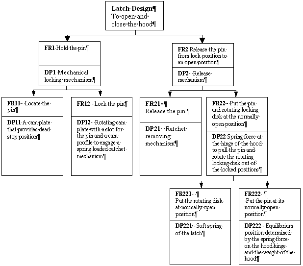
For instance, a hood latch example presented in (Suh 99) [14] on page 66, the design task is to hold a pin attached to the hood in the lock when the hood is closed and to release the pin to an open position when the hood is to be opened. By going through necessary zigzagging mapping procedures, the FR-DP tree of the hood latch design can be summarized and is shown in Figure 1.

This is a completely uncoupled design. According to the design axioms, this design is a good conceptual design. However, from the standpoint of design optimization (robust design) using Taguchi method, this design concept may need to be optimized further so that the hood latch performance is insensitive to the side effects of noise factors such as aging. What is the hood latch performance? In other words, what are the design intent and the system output response? In this design, spring is the energy resource and vital for the design functional requirements. In the mean time, the spring is also a potential problem due to its mechanical energy release impacting to the another components in the design, which will increase wear and unstable performance in long-term. Even though the conceptual design in this example is uncouple and good from the concept design structural (axiomatic design) standpoint, it is necessary to optimize the spring so that the spring force is insensitive to the system output response. Such optimization efforts could be achieved through robust parameter design. If we could make the spring force insensitive to the system output response which means we could select a spring with less spring force at the lowest possible costs and has much less impact side effects. The benefits of performing such efforts is same as one stone kills two birds in terms of reducing the sensitivity of spring force to system performance and desensitizing the side effects of noise factors. It is clear that the effort of identifying and selecting a proper system output response is important and vital for the successful design optimization.
From the Figure 1, we start with the lowest level of DPs like DP221 and DP222 and the corresponding FRs. With each level of component and subsystem, we review the design intent and the basic function. During this process, one key idea has to be kept in mind all the time is that we would like to optimize a system's functionality rather than a part or a system itself. The next question becomes how a corresponding FRs can be a system output response. If the existing functional requirements are not the best choice, what else could be considered? This has to be linked to the identification of system output response using substance-field analysis presented in the Part I. The Design Response Structural Analysis in Part I is used the best when a boundary of a system/subsystem is known. By reviewing each level of FR-DP tree in Figure 1, the summary of the possible system output responses for each level is shown in Table 1.
From the Table 1, we can see there are three levels of zigzagging mappings. At each level, there are identified possible system output responses and the input signals.
The possible subsystem output responses and the input signal are:
| At level 3: | System output response |
|
| Input signal: | Spring mechanical force | |
| At level 2: | System output response |
|
| Input signal |
|
|
| At level 1: | System output response |
|
| Input signal |
|
|
Sys-tem/ Subsystem Level |
System output Response |
FRS |
Dps |
System Input |
M M |
A A |
P T |
P R |
I I |
N X |
G |
|||
|
Material Information Energy |
FR1 |
FR2 |
FR11 |
FR12 |
FR21 |
FR22 |
FR221 |
FR222 |
||||||
|
1 |
FR1 |
Hold the pin |
DP1 |
Mechanical locking mechanism |
X |
|||||||||
|
Pin disengagement force |
FR2 |
Release the pin from lock position to an open position |
DP2 |
Release mechanism |
Force |
X |
||||||||
|
2.1 |
Pin location compared with target |
FR11 |
Locate the pin |
DP11 |
A cam plate that provides dead stop position |
X |
||||||||
|
Engagement force |
FR12 |
Lock the pin |
DP12 |
Rotating cam plate with a slot for the pin and a cam profile to engage a spring loaded ratchet mechanism |
X |
|||||||||
|
2.2 |
Pin disengagement force |
FR21 |
Release the pin |
DP21 |
Ratchet removing mechanism |
Ratchet travel distance |
X |
|||||||
|
Information |
FR22 |
Put the pin and rotating locking disk at the normally open position |
DP22 |
Spring force at the hinge of the hood to pull the pin and rotate the rotating locking disk out of the locked positions |
Mechanical force |
X |
||||||||
|
3 |
Information Displacement Disk rotation speed |
FR221 |
Put the rotating disk at normally open position |
DP221 |
Soft spring of the latch |
Mecha-nical force |
X |
|||||||
|
Information Displacement Pin disengagement force |
FR222 |
Put the pin at its normally open position |
DP222 |
Equilibrium position determined by the spring force on the hood hinge and the weight of the hood |
Mecha-nical force |
X |
Table 1. Summary of system input and output analysis
There are more than one possible system output responses in this example. Which one could be the right choice? With a couple of possible system output responses, let's review the basic function of this hood latch design. The design intent is to hold a pin attached to the hood in the lock when the hood is closed and to release the pin to an open position when the hood is to be opened. However, the basic function of this concept design is how the energy of spring force can be transformed smoothly to do the job in terms of closing and opening the pin consistently over the time. It is clearer now that the system output response should be the pin disengagement force and the input signal is the spring force. Having identified the proper system output response and the input signal, the effectiveness of design optimization can be improved significantly. The engineered diagram and the ideal function are shown in the Figure 2 and the Figure 3 respectively.
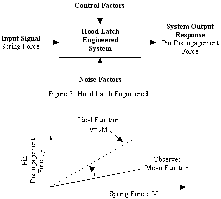
During the process of identifying the system output response, there is a lot of the information and decision-making go between the system, subsystems, components, FRs and DPs. This is one of the reasons how the process of identifying system output response can help to enhance the improvements of a concept design in the upfront design phase.
Usually, a given design may not be necessary uncoupled and not even decoupled. It should be pointed out that this example used here is somewhat ideal. The task of identifying a proper system output response becomes more challenging if a conceptual design is not uncoupled. By going through the procedures in the methodology of identification of system output response, we can be able to get clearer pictures about how a design can perform its basic function and plan for design optimization. More important benefit is to take the advantage of valuable feedback from the analyses of possible system output responses to improve a concept design. For example, using the same hood latch design, the original hood latch design was concerned with noise problem was a decoupled design. Such noise problem could have been improved if the methodology of identification of system output response was used without waiting the last minute result of testing (see Table 2, the level 1 and level 2 mapping in table 2 is same as in the Table 1). This is because the methodology of identification of system output response requires the understanding of design basic function and is concerned about how the energy can be transformed smoothly in an engineered system. Of course, this is not an easy task and has to be with certain experience and expertise in the interested areas.
|
System output Response |
FRs |
DPs |
System Input |
M M |
A A |
P T |
P R |
I I |
N X |
G |
Constraint |
|||
|
Material Information Energy |
FR1 |
FR2 |
FR11 |
FR12 |
FR21 |
FR22 |
FR221 |
FR222 |
Noise level should not exceed 50db |
|||||
|
FR21 |
Release the pin |
DP21 |
Ratchet removing mechanism |
X |
||||||||||
|
Energy Impact Noise Pin Travel Pin Speed |
FR22 |
Put the pin and rotating locking disk at the normally open position |
DP22 |
Spring force at the hinge of the hood to pull the pin and rotate the rotating locking disk out of the locked positions |
Mechanical force |
X |
||||||||
|
Energy Pin Travel Pin Speed |
FR221 |
Accelerate the pin (and hood) out of its closed position |
DP221 |
Heavy spring |
Mechanical force |
X |
||||||||
|
Energy Impact Noise |
FR222 |
Put the cam plate at normally open position |
DP222 |
Stopper |
X |
X |
Table 2. Hood latch original design
From Table 2, based on the analyses of system output response, we can know quickly that the impact noise could come from design parameter DP222 without having the test results.
By focusing on identifying possible system output responses and differentiating basic function from other non-basic function output responses, a great deal of information about the functional requirements and design parameters can provide a clue for engineers to improve a concept design as necessary. The benefits regarding design for testability would benefit from the methodology of identification of system output response, which is beyond the scope of this paper.
Our objective is to bridge the gap between conceptual design and parameter design by identifying proper system output response(s) to serve three main purposes:
To provide just-in-time feedback to improve concept design
To plan for robust parameter design
To improve the effectiveness of robust parameter design
In doing so, we can be able to facilitate the upfront robustness thinking and implement the strategy of robust conceptual design and robust parameter design.
3. DPs Coupling effects Assessments for this research
The additivity property of the effects of design parameter
with respect to a system output response is important for the robust parameter
design. In order to assess the additive effects of design parameters, we must
assess the coupling effects of design parameters. It is necessary to separate
the negative correlation from the positive correlation. This is because that we
would like to know how the similar physical effects could be combined so that
the energy can be transformed smoothly. For the purposes of this paper, we can
consider the negative coupling effects as an integer value between zero, two,
three four and five. Zero indicates no coupling effects at all, three indicates
moderate coupling effects and five indicates substantial effects. For the
positive correlations, we just would like to use the symbol ![]() indicates the strong relation,
indicates the strong relation, ![]() indicates the
medium correlation and
indicates the
medium correlation and ![]() indicates the weak
correlation between the DPs. These positive relationships are important for the
selection of system output response.
indicates the weak
correlation between the DPs. These positive relationships are important for the
selection of system output response.
The principle of coupling effects is proposed as means to accurately assess the magnitude of the potential interaction between two design parameters. A coupling effect occurs if the effect of a factor on the selected system output response changes under different levels of another factor (i.e. the effect of the first factor is not consistent under all conditions of the second factor. For example: In a baking process, if percent yield is used for the system output response, then the coupling effect is significant (Figure 4).

Figure 4. Example of Coupling Effects
It is essential to recognize that this initial interaction effects. The magnitude assessment is intended to predict the likelihood that a system output response will possess the additivity preferred. In addition, this step also aids the designer in considering the natural laws and inherent relationships that are likely to be the driving forces behind the coupling effects of DPs and the interactions between FRs. Thus, while optimizing a given concept, designer can be forewarned of areas of the design that will require extra and consideration when attempting to synthesize a solution that minimizes the coupling effect of DPs and the corresponding interactions between FRs. While it is true that this step can involve significant time and from the designer, it is believed that this early effort will facilitate more efficient robust parameter design synthesis and design analysis, reduce the need for re-optimization, and provide feedback for concept improvement that satisfy the independence axiom as well as the FRs.
It should be noted that the structure of this interaction assessment methodology is robust against understand estimating coupling effects. This is necessary to avoid missing critical potential relationships even though the designer may not possess a full understanding of what those relationships are or the extent of their effect. Accuracy of the procedure is based on a designer's experience, intuition, ability to visualize relationships and understanding of natural laws. Testing of the methodology will determine the level of difficulty encountered by the test subjects during the performance of the coupling effect assessments.
3.1 Construct the Matrix of DPs Coupling Effects
The interaction assessment procedure described in the previous section must be performed for each pair of DPs to completely represent the structure of the design problem. Completion of all pairwise interaction or correlation assessments yields a matrix of interaction magnitudes shown in Figure 5.
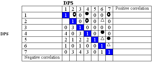
Figure 5: DPs Coupling Effects
It can be easily seen that the number of DP interactions (Q) that must be assessed is given by the equation:

Where N is the number of DPs in the design problem.
A quantitative assessment of overall independence (I)can be made from the following equation:
![]()
Where a value of I=1 indicates perfect independence and a value of M=0 indicates no independence between DPs.
Negative correlation (coupling effects) assessment indicates that the areas need more attention and the coupling effects must be reduced by selecting a proper system output response. Possive correlation assessments provides an opportunity to encourage engineers to investigate how the ways of energy transformation in the technical system could be grouped harmonly with a proper selection of system output response. Figure 4 offers a good overview on how some DPs may be combined based on the positive correlation.
In this step, we are not looking for numerical precise correlation but just collect all necessary information regarding the effects of DPs on a system output response based on the engineers' knowledge, experience, expertise and available data as much as possible.
3.2 Partitioning the Coupling Effects
We have now represented the identification of system output response as a matrix of coupling DPs and the positive correlations between the DPs while searching for possible system output response with the property of additive effects of DPs. When the DPs are strongly coupled, they should be partitioned such that highly coupled DPs are placed together within a partition while DPs with little coupling effects are placed in separate partitions. The resulting partitions yield smaller, relatively independent subgroup whose corresponding system output response can be more easily identified and synthesized by the engineer. An important attribute of the partitioning process is that it must focus on the identifiation of system output in terms of how the partition can help to regroup DPs such that the effects of regrouped DPs could be additive or monotonic on a system output response response and provide the feedback to improve the concpetual design.
By examining all possible system outputs, we would like to chose one system outpput reponse which will help to elminate or at least to reduce the coupling effects between DPs to the minimum level. We would like to partition the problem of identifying the system output response in a way that we can be able to reduce the complexity of the overall problem in terms of coupling effects and additivity while simultaneously highlighting the interactive portions of the problem that will require the most attention from the standpoint of finding relative less coupling effects of DPs with respect to a specific system output response being selected.
3.2.1 Partition Principle
Given a system output response being selected
Group design parameters with high level coupling effects within a group
Combine design parameters based on similar physica effect or the same energy transformation
Partition design parameters in such a way so that the positive effects can be grouped and the negative (coupling) effects can be reduced.
This partition principle is to say:
These design parameters could be decomposed into groups by sensitivity analysis. The analysis of variance (ANOVA) in terms of signal-to-noise (S/N) ratio could be utilized to conduct the sensitivity analysis.
The partition principle can be utilized to select a principle DP to satisfy a given FR based on the Independent Axiom. In the concpet design using axiomatic design approach is foucsed on how to find DPs to satisfy the given set of FRs. However, our focus is not to find DPs to satisfy the given FRs but to search a system output response to reduce the DPs coupling effects. Keep in mind that our intent is to identify a proper system output response for design optimization. The differnces between the conceptual design using design axioms and the identificaton of system output response are shown in the Table 3.
|
Conceptual Design (Top-down) |
Identification of SOR for Optimization (Bottom-up) |
||
|
Given |
A set of FRs |
Given |
A set of DPs |
|
Find |
A set of DPs |
Choose |
A System Output Response |
|
Assess |
FRs coupling effects |
Assess |
Coupling effects of DPs & possible positive correlation with respect to the chosen SOR |
|
Such that |
FR-DP mapping is 1 by 1 based on the independence axiom. |
Such that |
The coupling effects may be reduced and the positive effects may be combined or grouped. |
|
Final selection |
Based on the information axioms. |
Final selection |
Basic function based and the theorem of information (for optimization) |
Table 3. Comparison of procedures between conceptual design and Identification of system output response (SOR)
For the chosen system output response with the grouped strong coupling effects of DPs, assessing the principle DP and idenfitying the coressponding FR which may be the system output response we are searching for.
For example, in baking process, if the percent yield is used as a system output response, we know that the coupling effects between time and temperture will be stronge. By examining the function of time and temperture, we know the funciton of time or temperture is to provide necessary thermal energy for the baking process. Therefore, the energy related output response such as darkness may be identified as a proper system output response.
4. Mapping between Design Parameter and Physical Effects
Axiom 3 (Axiom of finite physical effects) [15]
We know that we cannot design anything that is incompatible with natural principle and laws. And we know that these well-known physical principles are finite. The finiteness of physical effects is true for a certain point of time, the state of art in natural science; finding new effects is concerned to be research in natural science.
With the partitioned design parameters, the coupling effect magnitudes that have been identified thus far represent the likelihood of a coupling effects based on known or assumed physical relationships between DPs in a selected system output response. We have now represented the problem of identifying system output response as a matrix of coupling DPs and the positive relationship of DPs. Based on the coupling effects matrix, engineer should try to understand the corresponding physical phenomena and effects.
Let Y be a system output response, PEi, i=1…m be possible physical effects, and g is the functional relationship between Y and PEi, then Y may be expressed as
y= f(DP1, DP2, …, DPn)=g(PE1, PE2,…, PEm) (4.1)
The domain of design parameter can be mapped to the domain of physical effects (Figure 6).
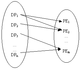
Figure6: Mapping from DPs to PEs
The mapping matrix may be expressed as follows (Figure 7):
Where
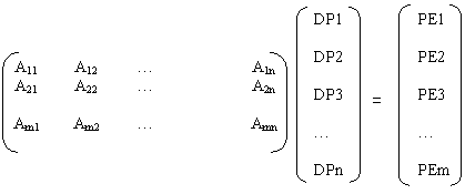
Aij; i=1,..n; j=1,…, m is the sensitivity coefficients between the design parameters and physical effects.
According to axiom 3, m is finite. This is important because we do not have to worry about countless physical effects, which we may not know at that time. By focusing on the major physical effects, we can be able to group and combine design parameters to decouple the coupling effects of design parameters with a given system output. Examining all possible alternative system output responses, we could select a system output response with better additive effects of design parameters.
For example, the catapult device shown in Figure 8 has a number of design parameters that have a high potential for coupling effects [13]. The objective of this device is to throw small objects and hit a certain target.
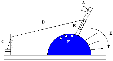
Figure 8
With the distance as a given output response, the design parameters are as follows:
Factor A: Release Cup Location-controls the geometric point of projectile release.
Factor B: Elastic Band Tie Point-controls the energy input to the system by varying the amount of band deflection
Factor C: Number of Rubber Bands-controls the energy input to the system by varying the spring rate, which controls the amount of energy stored per unit of pullback deflection.
Factor D: Elastic Band Stretch Point-controls the energy input to the system by varying the amount of band deflection
Factor E: Arm Stop Point-controls geometry of motion by constraining the arm motion and the geometric point of release.
Factor F: Pullback Angle-controls the energy input to the system by varying the amount of band deflection.
With the understanding of physics, the major physical effects are identified as follows:
PE1: Angle
PE2: Height
PE3: Speed
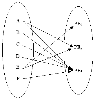
Figure 9: Mapping from DPs to PEs
From the figure 9, we can see that design parameters A and E may be decoupled by weakening or reducing effects on certain physical effects. Design parameters B, C, D, F may be combined or compounded for better, strong and smooth energy transformation. The mapping matrix may be written as (Figure 10):
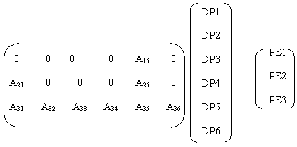
Figure 10: DPs &PEs Mapping Matrix
PE1=A15DP5 (4.2)
PE2=A21DP1+A25DP5 (4.3)
PE3=A31DP1+A32 DP2+A33 DP3+A34 DP4+A35 DP5+A36 DP6 (4.4)
From the equation (4.2)-(4.4) above, DP5, stop location, is the only design parameter controls the angle-physical effect. Physical effect PE2 is the coupled effects of DP1 and DP5. Physical effect PE3 is the sum of all design parameters. We can decouple the coupling effects of DP5 on PE2 and PE3 and the effects of DP1 on PE3 by minimizing the corresponding influences.
Since the only factor that controls the angle of release is the stop location, which is a critical control factor assignment. The stop location's influence on height and speed must be minimized to decouple the coupling effects. The efforts of minimizing the stop location's influence are feasible. By weakening the coupling effects and redefining some proper design parameter, the new mapping diagram can be modified as shown in Figure 11. G (catapult height) is a redefined new factor.
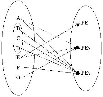
Figure 11: Mapping from DPs to PEs
Our intent is to identify a proper system output response by assessing the additive effects of parameters with a given system output response. Such additivity assessment must use engineering know-how knowledge and expertise. By evaluating all possible alternative system output responses in terms of the additivity, the better system output response can be identified and selected for less coupling effects among the design parameters. The additivity of the system output response being selected can be maximized.
5. Applying the Independence Axiom to the Physical Effects of DPs
The selection of system output response is now represented as basic function of the design intent and a partitioned coupling effect of DPs. The magnitudes of coupling effects that have been identified thus far represent the likelihood of a coupling effect based on known or assumed physical relationships between DPs in a given conceptual design. The DPs can be mapped to some of the finite physical effects. Within each mapped physical effects of a given system output response, the engineer must now strive to apply independence axiom to group and decouple the effects of DPs and apply information axiom to select the system output response. This is done by:
a. Identifying the basic function based system output response;
b. Identifying the coupling DPs per each physical effects and conceiving new design parameter that attempt to reduce or decouple those coupling effects;
c. Combining possible DPs with positive correlation and redefine the DPs
The designer can take comfort knowing that because of the first step in top-down approach through the zigzagging mapping which provides the opportunity to understand well the FRs and DPs. Any system output response being considered should be basic function based and have the maximum additive effects of DPs.
6. Synthesizing a System Output Response
The process of identifying system output response and synthesizing the design parameters for each system output response is the essence of optimization of technology and new product development. This subject is a topic of research and literature, the details of which have been somewhat simplified here. Taguchi [16] provides an excellent overview of relevant literature in the area of identification of system output response. He points that system output response is not given but has to be chosen. Phadke [7] cites the work of Taguchi and Fowlkes and Creveling [13] then enhances guidelines of identification of system output response widely addressed in the literature.
American Supplier Institute (ASI) 1989 promoted a theme that "to get quality, don't measure quality". This way of thinking is very important for the productivity of engineering activities. This involves understanding the problem and focusing on the critical engineering design intent. In the case of brake system, its function is to create torque, which causes deceleration. We should measure the relationship between the force of the driver's foot on the brake pedal (signal) and the torque generated (the system output response). Design may not be necessary optimized by minimizing the failures. However, optimized design can reduce failures automatically. This is because the input energy of a system can be transformed smoothly to the output energy without having "unintended energy" creating side effects. In parameter design, the most important job of the engineer is to select an effective characteristic to measure as data….We should measure data that relate to the function itself and not the symptoms of variability….Quality problems take place because of variability in the energy transformation. Considering the energy transformation helps to recognize the function of the system (Shin Taguchi) [6].
It is clear from the extent of the literature on the subject that there are some guidelines-the only state of art, which is not universally applicable to the steps of identification of system output response. As with top-down zigzagging mapping between FRs and DPs, and the bottom-up basic function search, coupling effect assessments, mapping between design parameters and physical effects, success in identification of system output response is a combination of an effective structured methodology and the designer's experience, intuition, and natural ability to conceive solutions.
System output response identification using the bottom-up structured system response analysis requires that a basic function be identified for system or subsystem and the physical effects be identified for each DP. When the designer has identified a system output response for the corresponding engineered system, the coupling effects of DP and the additivity of system output response must be examined and synthesized in the context of the overall engineered system. Adjustments will often be required due to non-ideal concept design structure based on the design axiom especially the unforeseen coupling effects of DPs and the unforeseen FR interactions or merely to ensure compatibility as solutions to the physical effects mapping are combined into a single holistic solution. The identified system output response should have a maximum additivity in terms of effects of design parameters and must be able to measure the engineered system's functional behavior rather than symptoms. The completion of this step marks the end of the first identification of system output response iteration.
Usually there may be couple of possible system output responses available for consideration. With the first iteration of identification of system output response in hand, the designer will examine the rest of possible system output responses and reassesses the physical effects of DP and the coupling effects and constructs an updated DP-PE mapping strategy. This is done same as previously described.
7. Applying the Information Axiom to the Selection of a System Output Response
The previously described design method may be repeated in order to identify and select a relative better system output response. Each of possible system output response is basic function based and has proper additivity with respect to the effects of design parameters to a certain extent as measured by the metric (I). The designer should then examine each possible system output response in light of optimization information theorem above (Suh's information axiom) in order to select the best system output response that can be used to optimize the system's functional behavior. Recall that the information axiom says that the best design that satisfies the independence axiom is the one that minimizes information content. This statement can be translated into the problem of system output response selection. That is the best system output response that has the maximum additivity is the one that minimizes information content. The meaning of information content in the design optimization problem is the probability of measuring design intent rather than symptoms such as failure rates, percent defect rates and etc. Information content is a predictor of relative complexity.
Exactly how to assess the level of information content in the selection of system output response is not obvious. As the number of possible system output response increases, the information (complexity) in terms of easy to measure, coupling effects of DPs, chain of action mode and the chain of physical effects required capturing the system's behavior increases.
El-Haik and Yang [17] addressed the issue of correlation in the axiomatic design. They defined a measure of complexity that is composed of three aspects: variability, correlation and vulnerability. Vulnerability relates to the design's size, interdependency of DPs (i.e. correlation), and the FR's sensitivity to changes in design parameters. This division of complexity in three parts gives, together with Boltzman's entropy measure, a formula for complexity. El-Haik and Yang have therefore proposed a new measure of complexity that accounts for correlation among DPs.
In contrast to the measure and formula proposed by El-Haik and Yang [17], Frey, Jahangir and Engelhardt [18] presented a means to compute information content as defined by [Suh90] while accounting for correlation and proved mathematically that the information content of a decoupled design is never exactly the sum of the information of the functional requirements. Decoupled designs always induce some correlation among the functional requirements even when the design parameters (DPs) are independent.
It is clear from the extent of the literature on the assessment of information content that there is no single measure that is universally applicable to the assessment of information content.
Thus if it is not feasible to assess the identified system output response on the basis of a quantitative measure of information content, we should instead seek a more qualitative approach. Suh (1990) defines information content as, " a measure of the probability of success of achieving the specified FRs (in the case of product design)…". Existing structured methods of identification of system output response allow the designer to do essentially the same thing. These methods assess the relative likelihood that a particular selected system output response will capture the system's behavior as compared to other competing system output responses. The system output response are then rated and ranked based on a measure similar to the information axiom.
One of the most widely used methods of design concept selection is that proposed by Pugh (1981). Pugh's method rates a set of proposed design concepts with respect to a selected datum concept. This idea can be adapted in the selection of system output response. The ratings are based on the relative ability of a system output response to satisfy a predetermined set of criteria such as additivity, easy to measure, constraints and overall independence and chain of effects. A rating can be either better than the datum (+), the same as the datum (S), or worse than the datum (-). A system output response comparison and evaluation matrix is generated that allows the identification of the best system output response(s). Pugh proposes that the overall selection effort be done by a relevant group and involve several iterations in which the datum system output response is changed. Again, this can be adapted in the system output response selection process. The goal is to see if a strong pattern of system output response emerges. From this one or more system output responses will usually tend to dominate.
In the context of system output response identification, the issues of information content as criteria for system output response selection must be considered at all subsequent stage of the design optimization (robust parameter design) through product life cycle. This includes detailed design, manufacturing, and etc. Assessing the information content at any of these phases requires input form the people who will be directly involved with the product at that phase.
8. Comparisons with other methods for the system output response
A competing method for the selection of system output response is the guidelines offered by Taguchi [Phadke89]. Taguchi suggests that the top priority of robust product design activities should always be on the improvement of product function. To accomplish this, energy-related system output response should be selected whenever possible. Five guidelines are suggested to serve the purpose to identify a proper system output response. Acknowledgment of the importance of the criteria in the guidelines is the key to understand the use of Taguchi methods. In general, it will be often be quite difficult to identify system output responses, which meet all of these criteria. Taguchi himself acknowledges this fact and states that the use of Taguchi methods will be inefficient to the extent that these guidelines are not satisfied.
In contrast to the guidelines suggested by Taguchi, the methodology of design response structural analysis presented in this paper offers more detail directions and activities to meet the criteria in the guidelines. The summary of major differences between the structural system output response identification and the guidelines for selection of system output response is shown in Table 4.
|
Features Methods |
Feedback to conceptual design |
Details for how to create a energy related response |
Assessment & decouple DPs' coupling effects |
Criteria for selecting SOR |
Nature of Approach |
|
Design Response Structural Analysis |
Blended top-down & bottom-up using framework of axiomatic design |
Offer four rules based on the substance-field theory |
Use both quantitative and qualitative approaches |
Use derived optimization theorem and corollary based on the design axioms and Pugh's method |
Scientific |
|
Guidelines |
No |
No |
Quantitative |
Experience |
State of art |
Table 4. The Summary of Design Response Structural Analysis and Taguchi' Guidelines
From the Table 4, it is obvious that the design response structural analysis method has significant advantages compared with the guidelines for the selection of system output response. Beyond the criteria in the suggested guidelines, the design response structural analysis offers the opportunity to enhance the robust conceptual design by facilitating the robustness thinking in the early design stage. Blending the top-down (conceptual design) and bottom-up (identification of system output response) approach will improve the quality of design in terms of:
Bridged the gap between conceptual design and parameter design
Improved robustness
Reduced time
Reduced costs
Reduced defects
Relaible
Improved testabilility
Satisfies requirements
Customer satisfaction
9. Conclusions
This paper has provided a scientific way of identifying system output response for the effective robust parameter design. The conceptual design robustness and the effectivenss of parameter design can be improved through the proper identificaiton of system output response in the upfront design stage. Therefore, the gap between the conceptual design and the parameter design can be minimized.
We have presented four rules in Part I based on the substnace-field analysis (TRIZ) for how to choose a system output response analysis. The first rule is the substance-field model development for system output response that encourages engineers to select or create an energy-related system output response. The second rule is to change the scope and boundary of technical system that helps engineers to thinks something outside the current system. The third and the fourth rules together suggest taking a deep consideration in the chain of action mode and the chain of effects to understand how the energy is formed or transformed. With these four rules, engineer can have more clear directions to identify a proper system output response.
Along with the four rules, the blending top-down and bottom-up for the identification of system output response approach using axiomatic design framework provides an environment for engineer to break down a system to a manageable subsystem and select a proper system output response for each corresponding subsystem. The identification of system output response, in terms of bottom-up system output response identification, is strengthened by knowledge gained from the assessment of DPs coupling effects, partitioning the DPs coupling effects and mapping out the DPs to their corresponding physical effects. The knowledge gained during the identification of system output response can feedback to the concept design immediately for the concept design improvement. The methodology of design response structural analysis has helped to serve two purposes:
to prepare for the robust parameter;
to improve the concept design robustness.
Therefore, the methodology of design response structural analysis can bridge the gap between the conceptual design and parameter design.
Compared with other approaches to identify the system output response, the approach presented in this paper offers more detail and specific steps with the proven theorem as the theoretical foundation. In other word, this approach is more scientific way rather than the state of art.
The presented approach was successfully applied to some very challenging case studies.
References
Suh, N.P., The principle of Design, New York, Oxford University Press, 1990.
Haug E.J. and Arora J.S., Applied Optimal Design, New York
Arora, J.S., Introduction to Optimum Design, New York: McGraw-Hill, 1989.
Haftka R.T., and Zafer G., Elements of Structural Optimization, Kluwer Academic Publishes, 1992.
Lee, K.W., Yi, J.W., Lee, K.H., Park,G.J., "A Structural Optimization Methodology Using The Independence Axiom", First International Conference on Axiomatic Design, Cambridge, MA, June, 2000.
Nair, V. N., "Taguchi's Parameter Design: A Panel Discussion." Technometrics 34 (2), 127-161 (1992)..,
Phadke, M.S., Quality Engineering Using Robust Design, Prentice-Hall, Englewood Cliffs, NJ, 1989.
Taguchi, G., System of Experiment Design, Vols. 1 and 2. ASI & Quality Resoureces, 1987.
Kar, A.K., "Linking Axiomatic Design and Taguchi Methods via Information Content in Design.", First International Conference on Axiomatic Design, Cambridge, MA, June, 2000.
Robust Design Using Taguchi Methods, Version 3, 1998, American Supplier Institute.
Lossack, I.R., Grabowski, H., "The Axiomatic Approach In The Universal Design Theory.", First International Conference on Axiomatic Design, Cambridge, MA, June, 2000.
Frey, D.D., Jahangir E., Engelhardt, F., "Computing The Information Content of Decoupled Designs." First International Conference on Axiomatic Design, Cambridge, MA, June, 2000.