|
|
|
|||||||||
|
|||||||||
By Val Kraev
Editor's note: Kraev's Korner was first published in the newsletter of the Altshuller Institute in 2005. Our thanks to the Altshuller Institute and the Technical Innovation Center for letting us reprint this educational series. Previous lessons can be found by searching the TRIZ Journal's archives.
TRIZ teachers and consultants are frequently asked about how TRIZ is used in companies. Most often people are interested in problems of how to apply TRIZ in conditions of a real manufacturing setting – the effects of this introduction, the tutoring of staff and concrete examples of its application. This chapter is dedicated to consideration of these questions. This program has as its objective the creation of a viable TRIZ organization within a company. As a rule, the representatives of the companies who inquire about TRIZ and its application already have certain information on this methodology and may even have experience with its use. Therefore, our talk starts with discussing how to obtain additional knowledge and education on TRIZ.
As shown in Figure 1, there are six basic directions of TRIZ application:
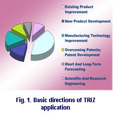
Companies within high-tech industries utilize TRIZ with the following objectives:
High-tech companies have similar objectives in the different segments of their business: semiconductors, LCD, mobile phone business (including development hardware and software for telecasting over the mobile phone), telecommunication network business, digital media business, home appliance business, R&D, etc.
Another important question is related to the integration of TRIZ utilization for technology or product prediction in concert with marketing and customers needs. TRIZ has been used successfully for technology and product prediction, integrated with customer needs through formulations of new technical contradictions that include customer requirements. For example, the customer/market would like to decrease noise of an air conditioner, but this requirement leads to complication of conditioner's design. By using TRIZ, this contradiction can be resolved on both technical and physical levels. Technically, it is solved with the application of insulation and composition foam materials. Physically, it can be resolved by neutralization of turbulent airflows.
TRIZ is used in conjunction with other methods at high-tech companies. Six Sigma is popular at many companies. Top management supports Six Sigma and many engineers become certified through the different Six Sigma courses. In the last three years, Six Sigma people have begun to understand that TRIZ can make up for the weak points of the Six Sigma process. While Six Sigma is efficient for finding problems that need resolution, TRIZ helps overcome those problems/contradictions. Six Sigma is efficient for finding the main factor of the problem but Six Sigma cannot always answer resolve those issues. At Samsung, employees consider Six Sigma statistical thinking, while TRIZ is inventive thinking. Many people now recognized the need for TRIZ to complement Six Sigma.
There are three basic groups of engineering problems, as shown in Figure 2 and explained here:
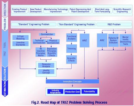
Fifteen independent TRIZ tools are present in Figure 2. Applying these tools leads to the development of solution concepts. After finishing this stage, the estimation of the obtained solution concepts is next. During estimation, each solution concept is evaluated by using specific criteria. The most frequently applied criteria include industry adaptability, production cost and patentability. The best concepts, as a rule, are verified and protected by international patents and other concepts are protected by national patents. Some concepts that do not meet requirements of estimation criteria are never patented.
The process of problem solving starts with an interview with the customer (often using a detailed questionnaire) and the defining of a problem statement. Typically, the situation that is described by the customer during the first interview has more than one problem – it is important to define ALL the problems. Next, select the customer's priority problem. A questionnaire provides valuable information including a detailed description of the problem situation, the problem development background, previous attempts for solving this problem by customer with a definition of the interactions, and links between and among the technological operations or components of the system.
A printer cartridge, as shown in Figure 3, consists of non-magnetic mono-components in a non-contact printing development system, consisting of an organic photo conductor drum, development roller and a gap between them. These components are placed inside a plastic housing.
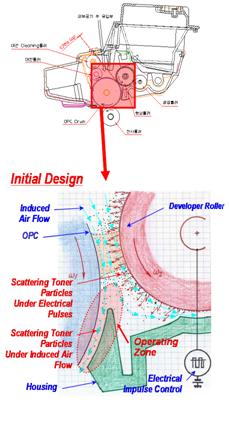
The non-contact process of printing is implemented by using high-voltage impulses with plus and minus potential. These impulses move negatively charged toner particles from a development roller (DR) to an organic photo conductor (OPC) drum, with part of the particles then returning to the roller. Some of the particles have a wrong positive charge, wrong signed toner (WST).
During the printing process, toner is scattered in the close space around the OPC, DR and housing. Toner particles are then carried out through the gap between the OPC and housing, and fall on the paper sheet. Therefore, the general quality of printing process is worsening. The main problem is: eliminating rejection of the toner particles outside the housing onto the paper sheets. The managerial statement of this project was: "It is necessary (with minimum modifications to the printer cartridge) to eliminate particle rejection while preserving the initial design and operating principles of the mechanism."
According to the process solving roadmap, this problem is classified as an existing problem improvement because it was related to development of a perfected product. Previous attempts to solve this problem with simple TRIZ tools (including inventive principles and standards) did not provide the required solution. Therefore, the problem was redefined as a non-standard engineering problem and solved with ARIZ.
In order to develop the model of a problem, the consolidated parts of ARIZ were used. According to this approach, the model consists of just two conflicting elements of the system, the product and tool – the technical contradiction between them and the function that should be provided by an x-element for solving the problem. The direct and reversed technical contradictions are formulated first. Then one technical contradiction is selected based upon the main desired function consisted in contradiction. (Remember that a technical contradiction describes the conflict between parameters within a system: improvement of one parameter of the system leads to the worsening of another parameter.)
In the printer example, technical contradiction 1 is that there is no gap between the OPC and DR (they are located with contact). Toner scattering is then absent, but printing resolution and image quality are worsening. Technical contradiction 2 is formulated as the opposite of the first contradiction: if there is a gap between OPC and DR, the printing resolution and image quality is improved, but toner particles are scattered outside between the OPC and paper housing.
The second of these contradictions is selected because this technical contradiction provides primary function for customer – obtaining the better printing resolution and image quality. The conflicting pair, then, is the gap between the OPC and developer/housing – and toner particles. (We cannot change the toner particles – the product, but we can modify the gap – the tool.) In order to solve the problem we need an x-element, change to the system, that keeps the gap between the OPC and developer/housing and eliminates the scattering of toner particles.
At this stage, the technical contradiction should be replaced with a physical contradiction. A physical contradiction results from opposing requirements to a physical characteristic of the single parameter or element in the system. Proper formulation of a physical contradiction usually shows the problem's nucleus and the ways for resolving the defined physical task, and eventually the whole problem. The step of formulating an ideal final result (IFR) helps to decide how to increase the beneficial factors and eliminate the harmful factors. Comparison of the developed solutions with the ideal result demonstrates whether the solving process is right in the choice of the major contradictions. The ideal solution serves as an abstract model and a goal for future specific solutions.
Speaking about developing ideal solutions for considered case we will start from transformation of the selected technical contradiction to the physical contradiction. The formulation of the physical contradiction must be related to one element only of an operating zone: into the gap between the OPC, developer and housing there should be airflow because this flow is induced by rotating the OPC and DR. There should not be airflow to eliminate particle rejection outside the housing.
Now we can formulate the ideal final result: The space in the gap between the OPC and housing (operating zone) itself eliminates scattering of toner particles by induced airflow during the printing process – saving induced airflow for performing the desired function.
During the generating the specific solution concepts stage, use existing resources first while working to achieve the IFR. In this case, electricity was the first proposed resource.
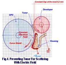
Figure 4 shows an electro-photographic image, forming a curved shield, is placed on the housing surface. This shield is located downstream of the developing roller, at a predetermined distance from the photosensitive medium on the OPC, and voltage is then applied. A controller regulates the voltage applied to the scattering preventive member, so as to transport the toner back to the photosensitive medium. The curved electrical shield makes a uniform constant electrical field between the OPT and the shield with a large extension. According to Coulomb's Law, the electrical field will push off charge toner particles with like charges to the OPC and does not allow them to exit the cartridge.
The option of using other available resources to solve this problem produced other ideas. One idea was to use directed airflow that removes toner particles from the induced flow, as shown in Figure 5. In other words, a new, directed airflow lends the developer roller the function of a fan or suction.
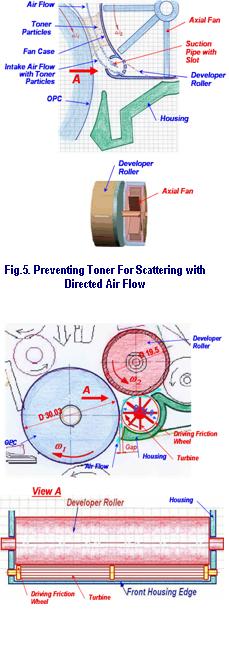
Two axial fans are located on the same axis with the developer. During roller rotation, the axial fans begin to boost (or suck) airflow with toner particles through a suction pipe with a slot. The suction pipe is located into the zone between the OPC and developer. The slot supplies a uniform distribution of suction airflow from the fans. The axial fans move airflow with particles through filters and housing windows. The filters capture the scattered particles and have a relatively large area for the minimal decrease of airflow resistance.
One more solution concept was proposed – to use an aerodynamic compensation of induced airflow in the gap between the OPC and housing, by applying oppositely directed airflow from a turbine (located between the OPC, housing and developer) as seen in Figure 6. There is a small gap between the OPC and turbine. The turbine rotates with the use of driving friction wheels that are located on one rotation axis.
During rotation, the turbine creates oppositely directed airflow. Since this airflow is going in the opposite direction to the induced flow with toner particles, a new summary flow is created. Therefore, turbine airflow blocks the induced flow with particles. The new summary airflow does not allow particles to go out through the gap between the OPC and housing. This new airflow (from the turbine with toner particles) goes into the recycle zone.
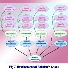
This case shows that one technical contradiction can be transformed to several different physical contradictions. Then, each physical contradiction can be solved by using several physical phenomena, by developing different designs for the printing cartridge. We developed the solution space (bluish color in Figure 7) with more than one new proposal. This situation is preferable for both an inventor and customer because they have several choices for future manufacturing, both costing less and enhancing the product's best performance. This multi-version designing also helps provide a good patenting policy for the customer. The different new anti-scattering methods and cartridge structures have been patented so as to provide a "patent fence" for the customer to protect his competitive advantage.
The structure of the solving process and further use of different TRIZ tools depend on the complexity of the engineering problem. Using TRIZ terminology, the three basic groups of problems are standard, non-standard, and research and development. The place of each TRIZ tool in the roadmap of the problem solving process is defined. Using the problem solving roadmap and consolidated algorithm of problem solving show how to develop solutions for the initial problem. The printer case study displays significance of multi-version designing by developing more than one solution concept for choices for manufacturing and strong patenting policy.
 | Problem Solution |
 | Sugar Problem This problem relates to the difficulty of measuring sugar. Very often during baking we need to get some exact amount of sugar (for instance, 100 grams) from a kilogram sugar bag. But what if there are no scales within easy reach? Try using a TRIZ standard – substitute one measurement with another one (standard 4.2.1). What kind of simple and easy measurement would work in this case? (Please, don't suggest taking scales from the neighbors, because they are not home.) |
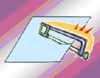 | Sawing Problem Sometimes it is necessary to saw a thin metal sheet with the help of a hack-saw. But it is not simple work! The thin sheet is distorting and vibrating under the force of the hack-saw. Therefore, we cannot saw this metal accurately and quickly. Obviously, for smooth sawing the metal sheet should be harder (shears and freezing do not work here) and should remain at the same level of hardness. This is a contradiction. What can be done to overcome it? |
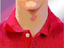 | Collar Problem We have to care about appearance of our garments, particularly during important meetings and discussions. But sometimes our clothes behave badly even if we do everything the manufacturer recommends. For instance, how to handle an unruly, curling collar on our knit sport shirts? No irons can stop it! The contradiction: the collar should be solid to prevent self-curling and should be naturally soft for keeping comfort and excellent appearance. Think about separations in the space and system. |
Val Kraev is the chief TRIZ officer of the Technical Innovation Center in Worcester, MA, USA, and has contributed several very valuable case studies to The TRIZ Journal. Contact Val Kraev at kraev (at) triz.org or visit http://www.triz.org.