By Abram Teplitskiy
Ice has specific inventive properties among its physical features. Two patents devoted to drainage technology will help illustrate its use.
Ice naturally has the ability to exist in two main technological conditions – solid state (ice) and liquid (water) states. It transfers from one state to the other at particular temperatures. Ice is perfect substance for exploring the use of the Theory of Inventive Problem Solving (TRIZ).
Patent One
On built-up land, water will appear on its surface from rains and other sources. It then goes down through the soil and accumulates in soil strata. Such water-saturated soil is less "capable" of keeping buildings in equilibrium positions. Sometimes it happens that when this water-saturated soil is combined with buildings with normal deformations, the buildings could be damaged. Preventing such accidents can be achieved by installing drainage pipelines under buildings and pumping out the collected water. Mostly metal or polymer pipes are used for these drainage purposes, which are perforated with holes according to project specifications.
The author worked with Dr. Rostislav Galich from the Ukraine in developing drainage construction technology by "frizzing" drainage materials in perforated tubes inside pipelines. A boring is drilled in water-saturated soil, into which a protective pipe is installed. To make such drainage pipes more effective, a granular drainage material is included inside the cylindrical casings. The drainage blocks (Figure 1) are then installed in vertical borings as a soil drainage system. When ice in the drainage blocks melts, the vertical drainage system has enough permeability (with its pre-added granular material) to conduct water down through the drainage system, pumping excess water outside of the protected area.
1 –drainage block; 2 – casing; 3 – bottom; 4 – water; 5 – lid;
6 – self-centering conical part; 7 – elastic elements; 8 – joining element
Soviet Union Patent # 1,444,470 |
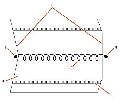
To strengthen the drainage sections on a longitudinal basis, spring elements are installed inside them as shown in Figure 2.
| Figure 2: Drainage Element with Spring |
|  |
|
1 – elastic section; 3-5 – lid; 7 – elastic element; 8 – connection device
Public Domain – Soviet Union Patent # 1,444,470 |
Figure 2's drainage follows the following procedures. A boring is drilled in the water-saturated soil and a casing tube is installed in the boring. During this time, drainage blocks are freezing and are installed in the casing. The ends include centering elements so that after the water is frozen, self-centering is realized. After this, the drainage blocks are ready to be installed in the vertical borings and consequently work as drainage. (Note – the pumping system is not shown in these figures.)
Patent Two
The other patent this article describes concerns a reconstruction site. The author and his co-workers faced a problem working on drainage reconstruction at a plant in the Ukraine. All kinds of conditions on a reconstruction site differ from those at a new construction site. In this case, the plant had more than 20 thousand personnel who needed to work continuously, while at the same time the existing drainage system needed to be fixed. The previous process was not enough for this situation as there existed drainage inside a pipeline that needing repairing.
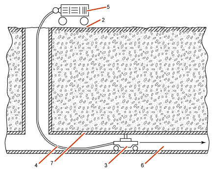
The wall of the pipeline needed to be perforated in order to fix the pipeline. The scheme of drainage perforation is shown in Figure 3.
| Figure 3: Perforation of Pipeline (Inside View) |
|  |
|
1 – pipeline; 2 – manhole; 3 – perforation device; 4 – hose; 5 – compressor;
6 – truss; 7 – holes; 8 – bundle of pipelines; 9 – drum; 10 – frozen blocks;
11 – soil; 12, 13 – pipelines; 14 – pipeline with permeable walls
Soviet Union Patent # 1,516,575 |
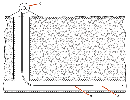
| Figure 4: Bundle of Flexible Pipelines Inside the Host Pipeline |
|  |
|
1 – pipeline; 2 – manhole; 3 – perforation device; 4 – hose; 5 – compressor; 6 – truss;
7 – holes; 8 – bundle of flexible pipelines; 9 – drum; 10 – block; 11 – local soil;
12, 13 – pipelines; 14 – pipeline with permeable walls
Soviet Union Patent #1,516,575 |
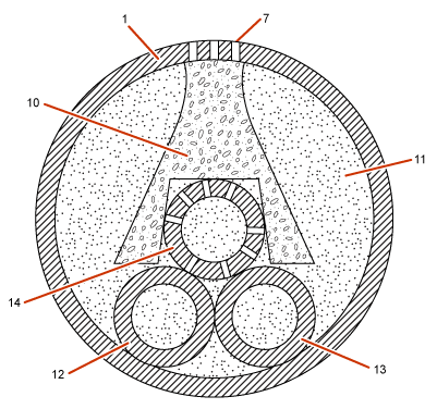
| Figure 5: Final Drainage Structure After Reconstruction |
|  |
|
1 – pipeline under reconstruction, 7-10 – granulated filter material,
11 – local fill soil; 12, 13 – pipelines
Soviet Union Patent # 1,516,575 |
The above-described technology proved effective and was widely implemented in the Ukraine for the reconstruction of drainage systems.
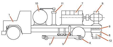
The machine shown in Figure 6 is used for cleaning iced surfaces of airfields, roads, etc. It includes a self-moving chassis and infrared radiation source. The effectiveness of this technology is based on the ability of ice to melt. | Figure 6: Machine for Ice Removal |
|  |
|
1– engine; 2 – road pavement; 4 – self-moving chassis
Russian Federation Patent # 2,205,918 |
The changing properties of ice allow for creative problem solutions.
Happy inventing!
Questions for Discussion
- What do these four cases have in common?
- What are the differences between the cases?
- What properties of ice are important to the solutions?
- Can you think of a home garden situation where one of these solutions would help?
About the Author:
Abram Teplitskiy, Ph.D., is a consultant for inventing, applied physics and civil engineering. Contact Abram Teplitskiy at tepl (at) sbcglobal.net.
Copyright © 2006-2011
– RealInnovation.com, CTQ Media. All Rights Reserved
Reproduction Without Permission Is Strictly Prohibited –
Request Permission
Publish an Article: Do you have a innovation
tip, learning or case study?
Share it
with the largest community of Innovation
professionals, and be recognized by your peers.
It's a
great way to promote your expertise and/or build your resume.
Read more about submitting an article.